Chapter 10
USE OF IRREGULAR FREQUENCY OPTION
WAMIT includes a method for removing the effects of irregular frequencies on both the velocity potential and the source strength. An outline of the method is given in Section 15.7, with more detailed information in References [8], [16] and [26]. In this method, the computational domain includes the interior free surface of the body and it is necessary to discretize both the body surface and the interior free surface. The integer parameter IRR controls the removal of the effect of irregular frequencies. Depending on the value of IRR, the discretization of the interior free surface may be provided by the user or it may be done automatically by the program. Explanation of the parameter IRR and the discretization of the interior free surface are given in the following Sections.
10.1 INPUT PARAMETERS
The parameter IRR is specified in the the configuration file as described in Section 4.7, with the default value zero. The definition of IRR is as follows.
IRR is the integer used to specify whether the effect of the irregular frequency is removed or not. The values IRR=(0,1,2,3) can be used in the low-order method (ILOWHI=0). Only the values IRR=(0,1,3) can be used in the higher-order method (ILOWHI=1). The definitions of each value are listed below, with details given in the following sections.
IRR= 0: Do not remove the effect of the irregular frequencies.
IRR= 1: Remove the effect of the irregular frequencies. The geometrical description of the interior free surface is included in the GDF file.
IRR> 1: Remove the effect of the irregular frequencies. The geometrical description of the interior free surface is provided automatically by the program. These options are described in Sections 10.2-4 below.
When NBODY>1 different values of IRR may be assigned for each body, following the format in Section 8.4. More specific information is given in Section 10.5.
If IRR= 1 in the low-order method (ILOWHI=0) the user must discretize the free surface. The coordinates of these panel vertices are included in the GDF file. The vertices of the free surface panels must be numbered in the clockwise direction when the panel is viewed from inside the body or in the counter-clockwise direction when the panel is viewed from above the free surface. The whole, half or a quadrant of the interior free surface must be discretized in accordance with the discretization of the body surface when there is geometric symmetry. The number of panels, the parameter NPAN in the GDF file, is the sum of the number of panels on the wetted surface of the body and the interior free surface. The order of the indices for the body panels and free-surface panels is not restricted in Version 7.
If IRR= 1 in the higher-order method (ILOWHI=1) the user must represent the interior free surface with one or more patches, in the same manner as for the body surface. This must be done with the normal pointing downward, in the negative z-direction. In the context of the right-hand-rule stated in Section 7.1, this is equivalent to requiring that the parametric coordinates (u,v) for the free-surface patch are defined such that the positive normal vector in the (u,v) plane points downward from the free surface into the body. The order of the indices for the free-surface patches and body patches is not restricted.
The subroutine CIRCCYL in GEOMXACT.F is an example where the interior free surface is represented analytically as one extra patch. Several other subroutines in GEOMXACT.F include similar options, with one or more patches on the interior free surface, as explained in the headers of these subroutines.
When IRR≥ 1, the convergence rate of the iterative solver (ISOLVE=0) is reduced. It is recommended to use either the block iterative solver or the direct solver.
The parameter ILOG in the POT file or the configuration file should be set equal to 1 when IRR≥ 1.
The generation of free-surface patches can generally be facilitated by using MultiSurf, as described in Appendix C.
In the low-order method, when IRR=1 and ISOR=0, it is recommended to discretize the interior free surface with the panels having the following properties: i) Panels have O(1) aspect ratio. ii) The length of the sides of the panels is similar to the waterline segments. When ISOR=1, the interior free surface panels should be discretized in a following manner. First, define a set of interior panels which are contiguous with the waterline segments, one panel for each segment, and having aspect ratios similar to the adjoining body panels. Continue this process recursively toward the centroid of the waterplane area. As the process continues moving inward toward the centroid, the panel size can be increased and the continuity between adjacent panels is less important.
10.2 AUTOMATIC FREE-SURFACE DISCRETIZATION (IRR=2 and ILOWHI=0)
If IRR=2 is input in the low-order method (ILOWHI=0) the program projects the body panels onto the free surface to generate panels on the free surface. The GDF file contains only the body panels (it is the same as the GDF file used with IRR= 0).
IRR=2 should not be specified for a body such as a Tension Leg Platform or semi-sub with pontoons, or more generally for any body where a vertical line intersects the body surface more than once and thus the projection of two body panels overlap on the free surface. A warning message is issued for any panel where the inward normal vector slopes downward, away from the free surface, unless the panel is entirely in the plane of the free surface. Panels which are entirely in the plane of the free surface are ignored. Dipole panels are ignored.
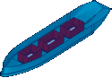
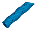
This simple procedure is effective for bodies such as the circular cylinder used in Test01, consisting of flat horizontal panels on the bottom (which are projected up to the interior free surface), and vertical panels on the sides (which are ignored in defining the interior free surface). Since dipole panels are ignored, this procedure can be applied for the spar with helical strakes used in Test09.
10.3 AUTOMATIC FREE-SURFACE DISCRETIZATION
(IRR=3 and ILOWHI=0)
If IRR=3 is input using the low-order method, the program automatically generates a discretized interior free surface and stores the panel vertices in a special output file gdf.idf. In this file, the vertices of the free surface panels are appended to the data in the GDF file. Since this automatic discretization cannot accommodate abnormal waterline shapes, the user should visualize the paneling on the interior free surface using the IDF file, to check the quality of the interior free surface discretization.
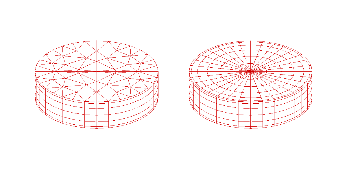
When ISOR=0 the interior free surface is discretized with triangular panels, based on the algorithm described in [8]. The sides of the triangular panels are similar to the average length of the waterline segments. An example is shown in the left figure of Figure 9.1.
When ISOR=1 the interior free surface is discretized in a regular pattern of quadrilateral panels, as shown in the right figure of Figure 9.1. Since the aspect ratio of the panels is O(1), the number of panels on the interior free surface is not so large as in the case ISOR=0. Connectivity between the free surface panels and the waterline segments is important in this case, as explained in [16]. The program first finds the centroid of the waterplane area enclosed by a waterline contour formed by a set of waterline segments. Then the two nodes of each waterline segment are connected to the centroid forming triangles with vertices on the centroid and on the two nodes. The triangles are discretized by quadrilateral panels (two sides of each panel are on the lines from the centroid to the nodes) from the waterline segments to the centroid with more dense discretization toward the waterline. The last panel is a small triangle which is used in the subsequent part of the program as a flag indicating the end of the connectivity. In this way, the connectivity is guaranteed between certain groups of panels starting from quadrilateral panels contiguous to waterline segment. This option should not be used for any body where a ray from the centroid of the waterplane area intersects the waterline more than once. In that case the option IRR=1 should be used.
When the option IRR=3 is used, special care is required in preparing the GDF file to ensure that there are no significant gaps between the vertices of adjacent panels at the waterline. In addition it is desirable to avoid panels at the waterline which are of extremely small dimensions. These requirements are best understood in the context of the procedure used by the program to define the waterline contour from the data in the GDF file.
As the first step for the automatic discretization of the free surface, the program searches for and identifies all of the waterline segments between the panel vertices which are in the plane of the free surface or within a specified small distance of this plane. If the nondimensional absolute value of the vertical coordinate is less than TOL=1.E-5 the vertex is defined to be in the plane of the free surface.
To avoid including very small segments, which would produce a nonuniform discretization, waterline segments are neglected if their lengths are smaller than a specified minimum length. The minimum length for this purpose is the product of another prescribed tolerance (TOL=10E-3) times the average length of the waterline segments. (In computing this average length, segments which are very small are neglected.) The program then rearranges the waterline segments in consecutive order, based on testing the distance between the end points of the segments. If this distance is less than the product of TOL times the average length, the program assumes the two segments are contiguous. When there is a gap larger than this product, the program outputs the error message ‘Waterline panels do not form a closed contour’. The parameter TOL=TOLGAPWL can be modified in the configuration files, as explained in Section 4.7.
Since waterline segments with a nondimensional length less than TOL are neglected, it is possible for this error message to be output even when the actual gap is less than TOL, due to the simultaneous occurrence of one or more gaps and/or small panels. More specifically, the error message is output when the cumulative length1 of successive small waterline segments is larger than the prescribed tolerance for the gap.
When this error message is encountered, the user is advised to re-discretize the body surface, to avoid panels with very small waterline segments and/or large gaps between adjacent panels, or alternatively to use the IRR=1 option which requires the user to discretize the free surface. It is also possible to overcome this problem on an ad hoc basis by modifying the parameter TOLGAPWL. Modification of this parameter is potentially dangerous, if there are relatively short waterline segments.
The parameter SCALEH is defined in WAMIT with the value 1.4. This parameter is used when IRR=3 and ISOR=0, to set the typical length ratio between the sides of the triangular panels on the free surface and the side of body panels.
10.4 AUTOMATIC FREE-SURFACE DISCRETIZATION
(IRR=3 and ILOWHI=1)
WAMIT includes the option to define the interior free surface automatically when the higher-order method is used (ILOWHI=1). This option can be used for multiple bodies, for bodies with trimmed waterlines, and for bodies with multiple waterlines such as TLP’s and Semi-Subs. It cannot be used for bodies with internal waterlines, such as moonpools. This option also cannot be used for some bodies with abnormal waterlines. It is strongly recommended to visualize the interior free surface, using the auxiliary output files described in Section 5.7, to ensure that the representation of this surface is appropriate.
When IRR=3, no other changes in the inputs are required relative to IRR=0. The GDF file should specify the number of exterior body patches NPATCH, not including the patches on the interior free surface. The optional SPL file should also refer only to the exterior body patches. After reading the GDF data the program searches for all patches which have one side in the free surface. These sides are connected into closed waterlines, or waterlines which end on one or two symmetry planes. The waterplane interior to each waterline is divided into patches which are bounded by the vertices of the exterior patches on the waterline, and by an interior axis on or near the center of the waterplane. The interior patches are mapped into parametric (u,v) coordinates with u = 1 on the axis, u = -1 on the waterline, and v increasing from -1 to +1 as one moves along the waterline in the positive direction (counterclockwise when viewed from above the free surface). The configuration parameter TOLGAPWL can be modified if necessary to define the allowable gaps between adjacent patches on the waterline.
Two alternative mappings are used to relate the Cartesian body coordinates x,y and parametric coordinates u,v, depending on the shape of the waterline along the outer edge of the patch. If the slope of this waterline segment changes sufficiently (greater than .5 radians over half of the segment) a polar mapping is used. Otherwise a ruled mapping is used, spanning the half-width between the axis and the waterline. When ruled mapping is used the axis must be parallel to the plane y = 0, as in the conventional choice of coordinates of ship-like hulls. Thus, when such bodies are to be analyzed, the longitudinal axis of the body should be parallel to the x - axis.
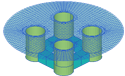
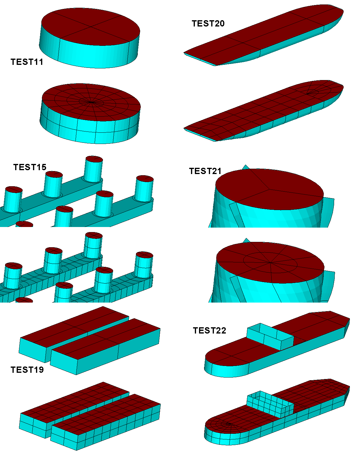
In general there is one interior patch for each exterior waterline patch. However if one or both ends of the waterline are straight lines within 0.1 radians of being perpendicular to the mapping axis, this segment is defined as the side v=-1 or v=+1 of the adjacent interior patch. Various examples of interior patches and panels are shown in Figure 10.2, corresponding to several of the standard test runs in the Appendix.
When the interior free surface patches are defined by the program, the spline control parameters assigned for each patch are the same as those input for the associated external patch, except that the parameter NU is increased or decreased based on the relative widths of the two patches. The parameter NV is the same as the corresponding exterior parameter (either NU or NV, depending on the orientation of the exterior patch), so the panel subdivisions are the same along the waterline. The spline control parameters for the interior patches are displayed in the header of the OUT file, when NBODY=1, following the panels of the exterior body surface. However when NBODY>1 these parameters are not output.
When the program connects adjacent sides of patches in the waterline, the patches are identified based on the coincidence or close proximity of their vertices. The parameter TOLGAPWL is used for this purpose, to allow for small gaps (or overlaps) between adjacent patches at the waterline. The default value TOLGAPWL=10-3 is used unless a different value of this parameter is defined in the CFG file, as explained in Section 3.7. In the test for adjacent patches the nondimensional Cartesian coordinates of the adjacent patch corners are evaluated, and the distance between these points is computed. The patches are assumed to be connected if this distance is less than either TOLGAPWL or the product of TOLGAPWL and the maximum length of one of the patch sides. The latter value is introduced to allow for cases where the size of the structure is much larger than the characteristic length ULEN. The default value is recommended in general. If the program is unable to close a waterline using this value, an error message is displayed stating that the waterline is not closed. In that case a larger value of TOLGAPWL should be input in the CFG file.
10.5 ASSIGNING DIFFERENT VALUES OF IRR FOR NBODY>1
It is possible to use different values of IRR for each body in a multibody analysis. The definition of IRR for each body is the same as in Sections 10.1-10.4. The format for inputting different values of IRR for each body, in the CFG file, is shown in Section 8.4. If the same value of IRR is used for all bodies it is not necessary to use the notation ‘IRR(n)=’, and one scalar value with the notation ‘IRR=’ can be input.
If the special notation ‘IRR(n)=’ is used in the CFG file, it is recommended to input values for each body explicitly, even if IRR=0 for some bodies. (The order of these inputs is arbitrary.) However this procedure is not required. If less than NBODY values of IRR(n) are included in the CFG file, the rules are as follows:
- Explicit lines of input must be included for IRR(n) with n = 1, 2,...,N, where N ≤NBODY.
- If N <NBODY, the remaining elements for N < n ≤NBODY are assigned with the same value as IRR(N)
For example, if NBODY=3 the inputs IRR(1)=1 and IRR(2)=3 will result in IRR(3)=3, whereas if IRR(1)=1 is the only input then all three elements are assigned IRR=1. Assigning only IRR(2) or IRR(3) will result in an error message and halt excution of the program.
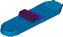
Test13a illustrates this scheme in the case where the cylinder is trimmed, and the spheroid is untrimmed. The interior free surface of the spheroid is generated by the subroutine ELLIPSOID in GEOMXACT.F. Since the cylinder is trimmed it cannot use the standard definition of the interior free surface generated by the subroutine CIRCYL. As shown in Appendix A.13, the GDF and SPL inputs for the spheroid are the same as one would used with IRR=1, whereas the inputs for the cylinder specify IRR=3 and do not include the interior free surface. In this case the interior free surface of the cylinder is elliptical, due to the trim angle, and different values of NU are assigned on the deep and shallow sides due to the corresponding depths of the exterior patches.