Appendix A
DESCRIPTION OF TEST RUNS
Translation of the manual to HTML format can cause errors in file formating. Please see the PDF version of the manual for correct formmating.
WAMIT V7.3 and V7.4 include 50 standard test runs, including 22 low-order and 28 higher-order applications. These are designed to illustrate various different options and features of WAMIT, and to help users to develop appropriate input files for their own purposes.
The following table gives relevant features of each test run. In this table the first column tst denotes the name of the test run. All of the corresponding input/output files are assigned the filenames TESTtst. (For example, the input POT file for the first test run listed below is TEST01.POT.) The first character of tst is 0 for low-order test runs (ILOWHI=0), and ≥1 for higher-order test runs (ILOWHI=1). Test runs which are for the same or similar bodies, except for different input options, are assigned the same number with a letter suffix. For example, TEST11 and TEST11a-c describe the same physical problem using different options to represent the geometry (B-splines, exact analytic formulae, MultiSurf, uniform and nonuniform mapping). In TEST14, the ISSC TLP is analysed and the use of the fixed mode option is illustrated. In TEST14a, the same geometry is analysed for a large number of input frequencies including zero and infinite frequencies and the outputs are postprocessed by the F2T utility. In TEST16 a rectangular barge is defined by the subroutine BARGE (IGDEF=-5), and in TEST16a the patches are defined by flat panels (IGDEF=0). Tests 17 and 17a-c illustrate alternative methods for analyzing a body with moonpools, as explained in Section A.17. Tests 01a, 09a, 13a and 22a are examples showing the use of trimmed waterlines (ITRIMWL=1).
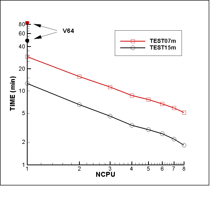
Various types of resonant motions are described in test runs 02, 03, 07, 17 and 22. These include moonpool pumping modes, small gaps between adjacent vessels, and tank sloshing. The use of damper lids and dipoles described in Section 12.8 is illustrated in these tests. For these tests a large number of closely-spaced wave periods, frequencies, or wavenumbers are required to describe the resonant features of the output, which are shown in the figures. Suitable arrays are shown in the corresponding .pot input files in each section below. However the standard digital form of these files distributed to users and available for download with the demonstration programs from the web site http:://www.wamit.com include much smaller arrays of periods, to reduce the run times and size of the output files. Users who wish to reproduce the more detailed results shown in the figures should edit the input files by copying the inputs shown in the sections below.
Some renumbering of the low-order test runs in previous versions was made starting in Version 7.3 to accommodate the new tests.
ILOWHI=0
| tst | description | other parameters |
| 01 | Circular cylinder | |
| 01a | Circular cylinder | ITRIMWL=1 |
| 01b | Circular cylinder | IRR=3 |
| 01c | Circular cylinder | ISOR=1 |
| 02 | Cylinder & moonpool | |
| 02a | Cylinder & moonpool with lid | IDAMPER=1 |
| 02b | Cylinder & moonpool with lid | IDAMPER=-1 |
| 03 | Two barges with small gap | |
| 03a | Two barges with damping lid | IDAMPER=1 |
| 03b | Two barges with dipole damper | IDAMPER=1 |
| 04 | Barge near wall | IWALLy0=1 |
| 04a | Barge in channel | CHANNEL_WIDTH=80.0 |
| 05 | Cylinder & spheroid | NBODY=2 |
| 05a | Cylinder & spheroid | NBODY=2, ISx=1 |
| 06 | ISSC TLP (coarse) | NPAN=128 |
| 06a | ISSC TLP (fine) | NPAN=1012 |
| 07 | FPSO with two tanks | |
| 07a | FPSO with dipole dampers in tanks | IDAMPER=1 |
| 07b | FPSO with tank and roll damping | IDAMPER=1, b44 = 1 × 10⁵ |
| 07c | FPSO with dipole dampers in tanks | IDAMPER=2 |
| 07d | FPSO with dipole dampers in tanks | IDAMPER=3 |
| 08 | Elastic column | NEWMDS=4 |
| 09 | Spar with strakes | NPDIPOLE=(673 960) |
| 09a | Spar with strakes | ITRIMWL=1 |
ILOWHI=1
| tst | description | other parameters |
| 11 | Circular cylinder | IGDEF=1 |
| 11a | Circular cylinder | IGDEF=-1 |
| 11b | Circular cylinder | IGDEF=-1, INONUMAP=1 |
| 11c | Circular cylinder | IGDEF=2 |
| 12 | Circular cylinder | IGDEF=-1, IRR=1 |
| 13 | Cylinder & spheroid | NBODY=2 |
| 13a | Cylinder & spheroid | NBODY=2, ITRIMWL=1 |
| 14 | ISSC TLP | IGDEF=-9 |
| 14a | ISSC TLP | NPER=101, IPERIN=2 |
| 15 | Semi-sub | IGDEF=-10 |
| 16 | Elastic barge | IGDEF=-5, NEWMDS=8 |
| 16a | Elastic barge | IGDEF=0, NEWMDS=8 |
| 17 | Cylinder & moonpool | IGDEF=-7, |
| 17a | Cylinder & moonpool with lid | IGDEF=-7, NEWMDS=2 |
| 17b | Cylinder & moonpool with lid damping | IGDEF=-7, NEWMDS=2 |
| 17c | Cylinder & moonpool with damper skirts | IGDEF=-34, IDAMPER=1 |
| 17d | Cylinder & moonpool with damper skirts | IGDEF=-34, IDAMPER=2 |
| 18 | Elastic column | IGDEF=-1, NEWMDS=4 |
| 19 | Catamaran barge | IGDEF=0 |
| 20 | MultiSurf barge | IGDEF=2 |
| 20a | MultiSurf barge in channel | IGDEF=2, CHANNEL_WIDTH=100.0 |
| 21 | Spar with strakes | IGDEF=-12, NPDIPOLE = 2 4 6 |
| 22 | FPSO with 2 tanks | IGDEF=-21, NPTANK=(8-11) (12-15) |
| 22a | FPSO with 2 tanks | ITRIMWL=1, XTRIM=(1.0, 0.0, 15.0) |
| 22b | FPSO with 2 tanks | ITRIMWL=1, XBODY(3)=-1.2 |
| 22c | FPSO with dipole dampers in tanks | IDAMPER=-1 |
| 22d | FPSO with dipole dampers in tanks | IDAMPER=2 |
| 23 | Bank of wavemakers | IGDEF=0, ISOLVE=-1, NEWMDS=8 |
| 24 | Motions of a hinged vessel | IGDEF=-32, NEWMDS=4 |
| 25 | ACV with two pressure chambers | IGDEF=0, NMODESFSP=2 |
Metric units are used in all of the test runs, and the gravitational acceleration is set equal to 9.80665 meters-per-second2.
Each test run is described briefly in the following sections. Also included in these sections are perspective illustrations of the complete underwater geometry, including reflections about the indicated planes of symmetry, and abbreviated listings of the input files. For the low-order tests the perspective figures show the subdivisions into panels. For the higher-order tests two perspective figures are included, to show the subdivisions into patches (upper or left) and into panels (lower or right).
All of the required input files for each test run, and the labeled output file (*.out) are included with the WAMIT software provided to licensed users. The same files can be downloaded with the demonstration programs from the web site http:://www.wamit.com. The input files for Test Run tst are named with the filename ‘testtst’ followed by the extensions .gdf, .pot, and .frc. The corresponding files fnames and config are given the same filenames with the extensions .wam and .cfg. (Some tests require additional input files, including the spline-control files .spl, control-surface files .csf, damper files .dmp, and data files with the extension .dat. The filenames for the data files are longer, starting with the same name ‘testtst’.)
The additional configuration file config.wam is included with the test files, and is intended to supplement the separate .cfg file for each test. The standard version of this file is as shown below:
RAMGBMAX=0.5
NCPU=1
USESRID_PATH=c:\wamitv7
The first line is a comment line which is ignored by the program. The parameters on the other lines are explained in Section 4.7.
Before running TESTtst, the user should copy the fnames files as follows:
- copy testtst.wam fnames.wam
as explained in Chapter 2. Alternatively, the batch file runtests.bat can be used to run all tests in succession.
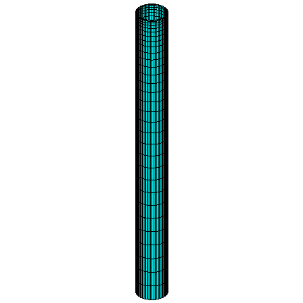
A.1 TRUNCATED VERTICAL CYLINDER – TEST01
The added-mass and damping coefficients, exciting forces, motions, wave elevations, field pressures, field velocities and drift forces are evaluated for a freely floating truncated vertical circular cylinder of radius 1 meter and draft 0.5 meters, in infinite water depth for three wave periods and one wave heading.
The origin of the coordinate system is located at the intersection of the vertical axis of the cylinder and the undisturbed position of the free surface. Using two planes of symmetry, only the first quadrant of the surface of the cylinder is discretized with 256 panels. 16, 8, and 8 panels are distributed in the azimuthal, radial, and vertical directions with equal spacing. The characteristic length is set equal to the radius of the cylinder. The cylinder center of gravity is located at the origin of the coordinate system, and the radii of gyration relative to its axes are taken equal to 1 meter.
test01.pot
test01.frc
test01.cfg
Input file: test01.cfg
! TEST01.CFG -- cylinder R=1, T=0.5, ILOWHI=0, IRR=0
ipltdat=5
ISOR=1 (omit ISOR in POT file, include source formulation)
ISOLVE=0 (use iterative solver)
ISCATT=0 (solve for total diffraction potential, not scattering)
ILOG=1 (omit ILOG in POT file, integrate log singularity)
IRR=0 (omit IRR in POT file, no irregular-frequency removal)
MONITR=0 (do not write FORCE output data to monitor)
NUMHDR=1 (write headers to numeric output files)
Input file: test01.pot
TEST01.POT -- cylinder R=1, T=0.5, ILOWHI=0, IRR=0
-1. HBOT
1 1 IRAD,IDIFF
3 NPER (array PER follows)
8.971402 2.006403 1.003033 PER
1 NBETA (array BETA follows)
0. BETA
1 NBODY
test01.gdf
0. 0. 0. 0. HBOT, XBODY(1-4)
1 1 1 1 1 1 IMODE(1-6)
First 10 lines of input file: test01.gdf
TEST01.GDF -- circular cylinder, R=1, T=0.5, ILOWHI=0
1.000000 9.806650 ULEN, GRAV
1 1 ISX, ISY
256 NEQN
0.0000000E+00 0.0000000E+00 -0.5000000
0.0000000E+00 0.0000000E+00 -0.5000000
0.1243981 1.2252143E-02 -0.5000000
0.1250000 0.0000000E+00 -0.5000000
0.1250000 0.0000000E+00 -0.5000000
0.1243981 1.2252143E-02 -0.5000000
TEST01.FRC Circular cylinder, ILOWHI=0, IRR=0
1 1 1 1 0 3 0 2 1
0.000000 VCG
1.000000 .0000000 .0000000
.0000000 1.000000 .0000000
.0000000 .0000000 1.000000 XPRDCT
0 NBETAH
2 NFIELD
1.5 0. 0.
1.5 0. -0.5 XFIELD
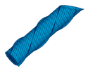
In TEST01A, the option to trim the waterline is specified with the parameters ITRIMWL and XTRIM included in the TEST01A.CFG file. The other input files are unchanged, but the filenames TEST01A.POT and TEST01A.FRC are used so that the output files will be named accordingly. The cylinder is rotated 15 degrees about the x-axis and elevated 0.27m, as shown in the lower figure below. The vertical elevation is required in this case since the gdf file only extends up to the original waterplane, and trimming in roll or pitch about the center without vertical displacement would submerge half of the waterline with a gap above it.
Input file: test01a.cfg
! TEST01A.CFG -- cylinder R=1, T=0.5, trimmed waterline
ilowgdf=1
ipltdat=5
ISOR=1 (omit ISOR in POT file, include source formulation)
ISOLVE=0 (use iterative solver)
ISCATT=0 (solve for total diffraction potential, not scattering)
ILOG=1 (omit ILOG in POT file, integrate log singularity)
IRR=0 (omit IRR in POT file, no irregular-frequency removal)
MONITR=0 (do not write FORCE output data to monitor)
NUMHDR=1 (write headers to numeric output files)
ITRIMWL=1
XTRIM= 0.27 0.0 15.
Input file: test01a.pot
TEST01A.POT -- cylinder R=1, T=0.5, trimmed waterline
-1. HBOT
1 1 IRAD,IDIFF
3 NPER (array PER follows)
8.971402 2.006403 1.003033 PER
1 NBETA (array BETA follows)
0. BETA
1 NBODY
test01.gdf
0. 0. 0. 0. HBOT, XBODY(1-4)
1 1 1 1 1 1 IMODE(1-6)
Input file: test01a.frc
TEST01A.FRC Circular cylinder, trimmed waterline
1 1 1 1 0 3 0 2 0
0.000000 VCG
1.000000 .0000000 .0000000
.0000000 1.000000 .0000000
.0000000 .0000000 1.000000 XPRDCT
0 NBETAH
2 NFIELD
1.5 0. 0.
1.5 0. -0.5 XFIELD
TEST01b illustrates the use of the irregular-frequency option described in Chapter 10. The geometry and most other inputs are the same as in TEST01. The parameter IRR=3 is set to use automatic panelization of the interior free surface. Wave periods are chosen so that the wave frequencies are near the first and second irregular frequencies of the cylinder. The direct solver (ISOLVE=1) is used since the iterative and block-iterative solvers do not converge reliably for the source formulation (ISOR=1).
The GDF input is the same as TEST01.GDF. The additional panels on the interior free surface, which are generated automatically by the program, are shown in red in the Figure below.
Input file: test01b.cfg
! TEST01b.CFG -- Circular cylinder, ILOWHI=0, IRR=3, direct solver
ilowgdf=1
ipltdat=5
IRR=3
ISOR=1
ISOLVE=1
ILOG=1
MONITR=0
NUMHDR=1
Input file: test01b.pot
TEST01b.POT -- Circular cylinder, ILOWHI=0, IRR=3
-1. HBOT
1 1 IRAD,IDIFF
2
1.182288 1.003025
1
0.0
1 NBODY
test01b.gdf
0.0 0.0 0.0 0.0
1 1 1 1 1 1
First 10 lines of input file: test01b.gdf
TEST01b.GDF circular cylinder, R=1, T=0.5, ILOWHI=0, IRR=3,
1.000000 9.806650
1 1
256
0.0000000E+00 0.0000000E+00 -0.5000000
0.0000000E+00 0.0000000E+00 -0.5000000
0.1243981 1.2252143E-02 -0.5000000
0.1250000 0.0000000E+00 -0.5000000
0.1250000 0.0000000E+00 -0.5000000
0.1243981 1.2252143E-02 -0.5000000
Input file: test01b.frc
TEST01b.FRC -- Circular cylinder, ILOWHI=0, IRR=3
1 1 1 1 0 3 0 1 1
0.000000
1.000000 .0000000 .0000000
.0000000 1.000000 .0000000
.0000000 .0000000 1.000000
0
2
1.5 0.0 0.0
1.5 0.0 -0.5
TEST01c illustrates the use of the source formulation (Section 5.2) to determine the mean drift force and moment from local pressure integration. The motions and the drift forces are evaluated for a freely floating truncated vertical circular cylinder of radius 1 meter and draft 1 meter, in a water depth of 7.14 meter for four wave periods and one wave heading.
The origin of the global coordinate system is located at the intersection of the vertical axis of the cylinder and the undisturbed position of the free surface. The origin of the body fixed coordinate system is shifted -0.515 meters under the free-surface. Using two planes of symmetry, the first quadrant of the surface of the cylinder is discretized with 288 panels. 12, 8, and 16 panels are distributed in the azimuthal, radial, and vertical directions with cosine spacing at the free surface and corner. The characteristic length is set equal to the radius of the cylinder. The cylinder center of gravity is located at the origin of the body coordinate system, and the radii of gyration relative to its axes are shown in the FRC file.
All three options (IOPTN 7,8,9) are included in the FRC file. For option 7, where the drift force and moment are evaluated from the method described in (Chapter 11), the control surface is a co-axial cylinder with radius and draft 2 meters as specified in the file test03.csf. In option 8 the horizontal drift force and vertical moment are evaluated based on the momentum at infinity, but this method cannot be used for the vertical force or horizontal components of the moment. In option 9 the mean pressure is integrated over the body surface. Generally speaking, the evaluation of mean drift forces is more accurate when one of the momentum conservation methods is used, especially for bodies with sharp corners where the local velocity and second-order pressure are singular. Comparison of the outputs shows that they are in good agreement, except for the second wave period which is close to the heave resonance frequency, where the vertical drift force computed in option 7 is quite accurate but the output in option 9 contains a large error. This is due to cancellation between two large contributions of opposite signs (the second integration in equations (12.47) and (12.48)), when the heave motion amplitude is large. In the FRC file IOPTN(7)=-1 is assigned to use the source formulation (ISOR=1) in option 7.
Input file: test01c.cfg
! TEST01c.CFG Cylinder, R=T=1, ILOWHI=0, ISOR=1
ilowgdf=1
ipltdat=5
ISOR=1
ISOLVE=0
ISCATT=0
ILOG=0
IRR=0
MONITR=0
NUMHDR=1
Input file: test01c.pot
TEST01c.POT Cylinder, R=T=1, ILOWHI=0, ISOR=1
7.14 HBOT
1 1 IRAD,IDIFF
4
2.837491 2.398118 2.006409 1.638226
1
0.0
1 NBODY
test01c.gdf
0.0 0.0 -0.515 0.0
1 1 1 1 1 1
TEST01c.GDF Cylinder, R=T=1, ILOWHI=0, ISOR=1
1.000000 9.806650
1 1
288
0.0000000E+00 0.0000000E+00 -0.4850000
0.0000000E+00 0.0000000E+00 -0.4850000
0.1934213 2.5464399E-02 -0.4850000
0.1950903 0.0000000E+00 -0.4850000
0.1950903 0.0000000E+00 -0.4850000
0.1934213 2.5464399E-02 -0.4850000
Input file: test01c.frc
TEST01c.FRC Cylinder, R=T=1, ILOWHI=0, ISOR=1
0 0 0 1 0 0 -1 1 1
0.000000
0.742000 0.000000 0.000000
0.000000 0.742000 0.000000
0.000000 0.000000 1.000000
0
0
Input file: test01c.csf
test01c.csf higher-order csf file, circular outer boundary
1 ILOWHICSF
1 1 ISX ISY
0 0 1. NPATCSF ICDEF PSZCSF cf section 11.5, page 11-12
2.0 2.0 RADIUS, DEPTH
0 NPART
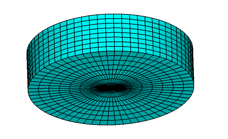
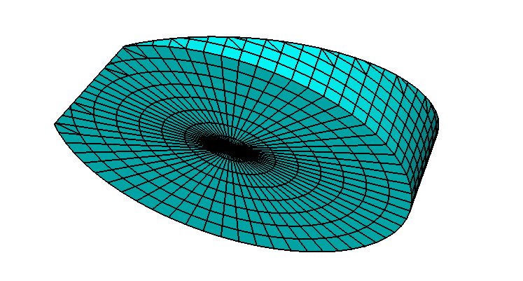
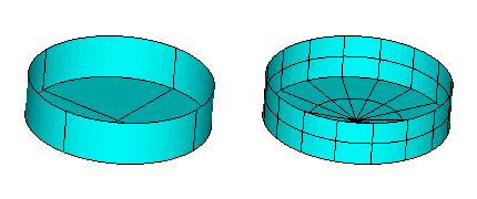
A.2 CYLINDER & MOONPOOL – TEST02
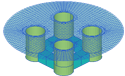
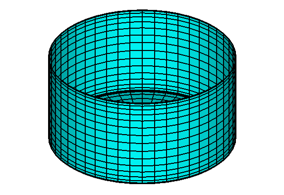
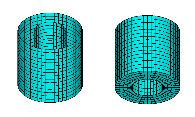
Test02 analyzes a cylinder with a moonpool, as shown in the figures below (viewed from above in the left figure and from below in the right figure). The same cylinder is analyzed using the higher-order method in Section A.17. The outer radius of the cylinder is 0.5m, the radius of the moonpool is 0.25m, and the draft is 1.0m. Special attention is given to the resonant heave motion and vertical ‘pumping mode’ in the moonpool. These occur near the wave period where Kd = 1 where K is the wavenumber and d is the draft, or where the wavelength is 2πd. Thus the wave period is replaced by the wavenumber in the .pot file using the option IPERIN=3 in the .cfg file, and a large number of closely-spaced wavenumbers are included to define the response near resonance. The calculations are performed for head waves (β = 270∘) with three degrees of freedom (surge, heave, pitch) specified by the array IMODE.
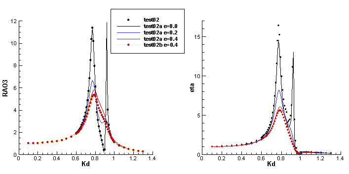
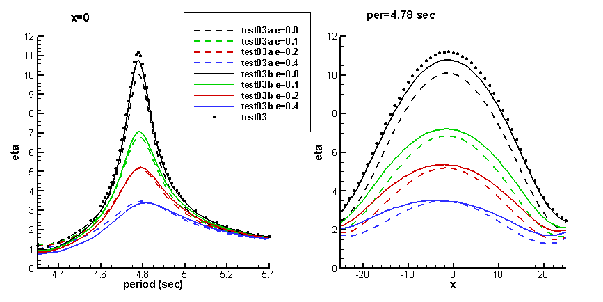
The resulting heave amplitude and free-surface amplitude at the center of the moonpool are shown by the filled black circles in Figure A.1. The two sharp peaks are due to coupling between the heave and moonpool motion. As noted on page A-1, the results shown in this Figure are based on the larger array of wavenumbers included in the version of the input files test02.pot, test02a.pot and test02b.pot shown below.
Input file: test02.cfg
! TEST02.CFG -- cylinder with moonpool
ipltdat=1
ISOLVE=1
IPERIN=3 (input wavenumber)
IPEROUT=3 (output wavenumber)
NUMHDR=1
Input file: test02.pot
TEST02.POT -- cylinder with moonpool
-1.
0 0 IRAD, IDIFF
57
0.100000 0.150000 0.200000 0.250000 0.300000
0.350000 0.400000 0.450000 0.500000 0.550000
0.600000 0.610000 0.620000 0.630000 0.640000
0.650000 0.660000 0.670000 0.680000 0.690000
0.700000 0.710000 0.720000 0.730000 0.740000
0.750000 0.760000 0.770000 0.780000 0.790000
0.800000 0.810000 0.820000 0.830000 0.840000
0.850000 0.860000 0.870000 0.880000 0.890000
0.900000 0.910000 0.920000 0.930000 0.940000
0.950000 0.960000 0.970000 0.980000 0.990000
1.000000 1.050000 1.100000 1.150000 1.200000
1.250000 1.300000
1 NBETA (array BETA follows)
180.
1 NBODY
test02.gdf
0. 0. 0. 0. XBODY
1 0 1 0 1 0 IMODE(1-6)
First 10 lines of input file: test02.gdf
TEST02.gdf cylinder with moonpool
1.000000 9.806650
1 1
368
0.4957224 6.5263107E-02 0.0000000E+00
0.5000000 0.0000000E+00 0.0000000E+00
0.5000000 0.0000000E+00 -6.2500000E-02
0.4957224 6.5263107E-02 -6.2500000E-02
0.4829629 0.1294095 0.0000000E+00
0.4957224 6.5263107E-02 0.0000000E+00
Input file: test02.frc
TEST02.FRC -- Cylinder with moonpool
1 1 1 1 0 1 0 0 0 IOPTN(1-9)
0.000000 VCG
0.500000 .0000000 .0000000
.0000000 0.500000 .0000000
.0000000 .0000000 0.500000 XPRDCT
0 NBETAH
1 NFIELD
0.0 0.0 0.0
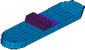
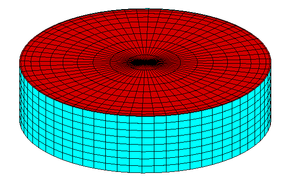
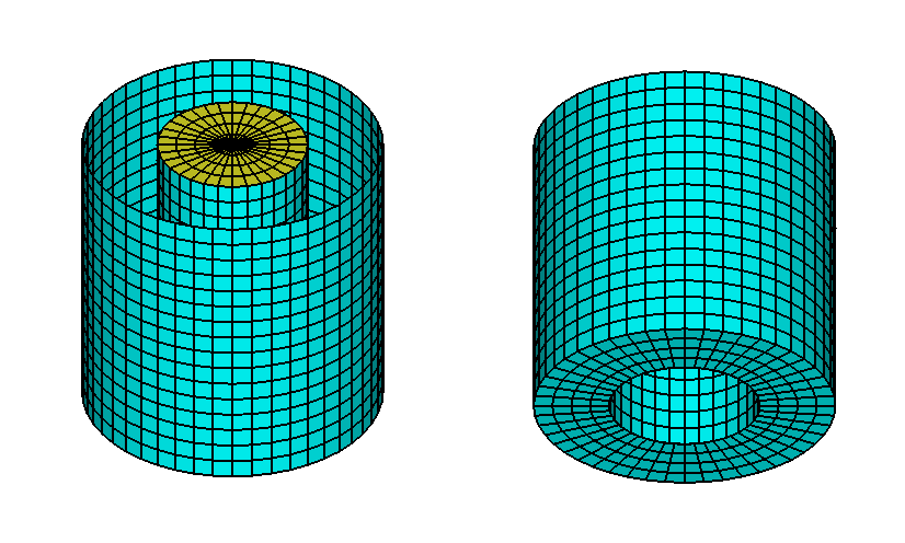
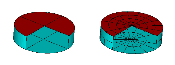
In TEST02a and TEST02b a damper lid is added on the moonpool free-surface as shown in the figure below. For these tests NPERGROUP is used in the .pot files to assign the array of wavenumbers in test02.pot in a more compact manner as described in Section 4.2. The lid is represented by 32 × 4 = 144 panels, with 32 in each quadrant. These are included at the end of the file test02a.gdf. The external damping option described in Section 12.8 is used, with IDAMPER=1 in test02a.cfg and IDAMPER=-1 in test02b.cfg. Since the other inputs are the same, test02a.gdf and test02a.dmp can be used for both runs, with test02a.gdf specified in test02b.pot. The file test02a.dmp includes the number of dampers (1), the first and last panel indices, and the value of the damping parameter EDAMPER. EDAMPER can be changed to give the results shown in Figure A.1.
The Haskind exciting force is not valid if IDAMPER>0. Thus ioptn(4)=2 is assigned in test02a.frc to evaluate the RAO’s from the diffraction exciting force, and the same option is used in test02b although this is not necessary when IDAMPER=-1.
Since the horizontal extent of the moonpool free surface is relatively small, it is sufficient to use only two modes corresponding to heave and pitch of the lid relative to the body. The subroutine MOONPOOL_FS in the NEWMODES subroutine is used, specified by IGENMDS=17 in test02b.cfg with NEWMDS=2 to denote that there are two generalized modes.
In TEST02 the free-surface amplitude is computed at the field point (0.0 0.0 0.0). This is not possible with the lid on the free surface, and various alternatives exist to compute the elevation in this case. In test02a and test02b a simple but approximate alternative is used, with the field point submerged at (0.0 0.0 -0.1).
Input file: test02a.cfg
! TEST02a.CFG file, cylinder with lid, idamper=1
ipltdat=1
ILOG=1
ISOLVE=1
IPERIN=3 (input wavenumber)
IPEROUT=3 (output wavenumber)
NUMHDR=1
idamper=1
Input file: test02a.pot
TEST02a cylinder with moonpool, ilowhi=0
-1.
0 0 IRAD, IDIFF
NPERGROUP=3
-11
0.10 0.05 (end of group 1, K = 0.10 to 0.60)
-40
0.61 0.01 (end of group 2, K = 0.61 to 1.00)
-6
1.05 0.05 (end of group 3, K = 1.05 to 1.50)
1 NBETA (array BETA follows)
180.
1 NBODY
test02a.gdf
0. 0. 0. 0. XBODY
1 0 1 0 1 0 IMODE(1-6)
First 10 lines of input file: test02a.gdf
TEST02a.gdf cylinder with moonpool + lid on free surface
1.000000 9.806650
1 1
400
0.4957224 6.5263107E-02 0.0000000E+00
0.5000000 0.0000000E+00 0.0000000E+00
0.5000000 0.0000000E+00 -6.2500000E-02
0.4957224 6.5263107E-02 -6.2500000E-02
0.4829629 0.1294095 0.0000000E+00
0.4957224 6.5263107E-02 0.0000000E+00
Input file: test02a.dmp
test02a.dmp file, edamper=0.4
1 ndampers
369 400 npdamper
0.4 edamper
Input file: test02a.frc
TEST02a.FRC Cylinder with moonpool
1 0 1 2 0 1 0 0 0 IOPTN(1-9)
0.000000 VCG
0.500000 .0000000 .0000000
.0000000 0.500000 .0000000
.0000000 .0000000 0.500000 XPRDCT
0 NBETAH
1 NFIELD
0.0 0.0 -0.1
Input file: test02b.cfg
! TEST02b.CFG file, cylinder with lid, idamper=-1
ipltdat=1
ILOG=1
ISOLVE=1
IPERIN=3 (input wavenumber)
IPEROUT=3 (output wavenumber)
NUMHDR=1
idamper=-1
IGENMDS=17
NEWMDS = 2
Input file: test02b.pot
TEST02b cylinder with moonpool + lid, ilowhi=0
-1.
0 0 IRAD, IDIFF
NPERGROUP=3
-11
0.10 0.05 (end of group 1, K = 0.10 to 0.60)
-40
0.61 0.01 (end of group 2, K = 0.61 to 1.00)
-6
1.05 0.05 (end of group 3, K = 1.05 to 1.50)
1 NBETA (array BETA follows)
180.
1 NBODY
test02a.gdf
0. 0. 0. 0. XBODY
1 0 1 0 1 0 IMODE(1-6)
Input file: test02b.dmp
test02b.dmp file, edamper=0.4
1 ndampers
7 8 nmddamper
0.4 edamper
Input file: test02b.frc
TEST02b.FRC Cylinder with moonpool
1 1 1 2 0 1 0 0 0 IOPTN(1-9)
0.000000 VCG
0.500000 .0000000 .0000000
.0000000 0.500000 .0000000
.0000000 .0000000 0.500000 XPRDCT
0 NBETAH
1 NFIELD
0.0 0.0 -0.1
A.3 TWO BARGES WITH A SMALL GAP – TEST03
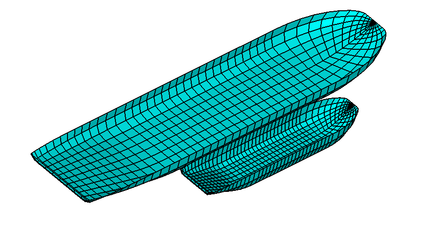
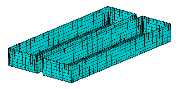
The two barges shown in the figure below are similar to the MultiSurf barge in Section A.20. The larger barge has a length of 100m, beam 20m, and draft 4.8m. The smaller barge has a length of 50m, beam 10m, and draft 4.8m. The gap width between the two barges is 2m along the parallel middle-body of the smaller barge. Special attention is given to the problem of gap resonance, where vertical motions and free-surface elevations of large amplitude occur, as shown in Figure A.2.
The multiple-body analysis described in Chapter 8 is used, with NBODY=2 in Test03. In Test03a and Test03b damping surfaces are added in the gap, using a lid on the free surface and a submerged dipole damper respectively. Only the diffraction solution is considered, corresponding to the situation where the two barges are fixed with no rigid-body motions. Beam seas are assumed, incident from the side of the smaller barge, so that the gap resonance is maximized. A large number of closely-spaced wave periods are used as in Section A.2, and these are input in the pot files with the NPERGROUP option.
Each barge is symmetrical about it’s transverse axis but not in the longitudinal direction. Thus ISX=0 and ISY=1 in the gdf files. Transverse offsets -11.0m and 6.0m are specified in the corresponding XBODY arrays in the pot file. The two half-bodies are reflected by the program, as explained in Section 8.5.
Input file: test03.cfg
! TEST03.CFG -- 2 barges alongside, NBODY=2, ILOWHI=0
IPLTDAT=1
NUMHDR=1
ISOLVE=1
NOOUT=0 1 1 1 0 1 1 1 1
TEST03.POT -- 2 barges alongside
-1.0 HBOT
-1 1 IRAD,IDIFF
npergroup=3
-6
4.3 0.05
-40
4.6 0.01
-9
5.0 0.05
1 NBETA
270.0 BETA
2 NBODY
test03b1.gdf
0.0 -11.0 0.0 0.0
1 1 1 1 1 1
test03b2.gdf
0.0 6.0 0.0 0.0 0.0
1 1 1 1 1 1
First 10 lines of input file: test03b1.gdf
Test run for 100m barge modelled with MultiSurf
1.000000 9.806650
0 1
284
-45.21144 0.0000000E+00 -0.7666667
-46.45135 0.0000000E+00 -1.3509452E-07
-46.45135 0.0000000E+00 -1.3509467E-07
-45.42501 0.1568997 -0.6435185
-43.87196 0.0000000E+00 -1.466667
-45.21144 0.0000000E+00 -0.7666667
First 10 lines of input file: test03b2.gdf
Test run for 50m barge modelled with MultiSurf
1.000000 9.806650
0 1
284
-22.60572 0.0000000E+00 -0.7666667
-23.22567 0.0000000E+00 -1.3509452E-07
-23.22567 0.0000000E+00 -1.3509467E-07
-22.71251 7.8449845E-02 -0.6435185
-21.93598 0.0000000E+00 -1.466667
-22.60572 0.0000000E+00 -0.7666667
Input file: test03.frc
TEST03.FRC -- 2 barges alongside
0 0 1 0 0 1 0 0 0
0.000000 VCG
1.000000 .0000000 .0000000
.0000000 1.000000 .0000000
.0000000 .0000000 1.000000 XPRDCT
0.000000 VCG
1.000000 .0000000 .0000000
.0000000 1.000000 .0000000
.0000000 .0000000 1.000000 XPRDCT
0 NBETAH
1 NFIELD
0. 0. 0. XFIELD
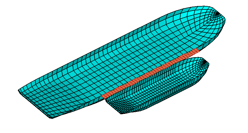
In TEST03a a lid damper is added in the gap on the free surface, as shown in the figure below. This is a rectangular surface with the same length as the smaller barge, filling the gap along the parallel middle-body. The lid is considered to be a third body, which is symmetrical about the planes x=0 and y=0. Thus only one quadrant with 40 panels is included in the file test03lid.gdf with the symmetry indices ISX=ISY=1. The gdf files for the two barges are the same as in TEST03. The parameter IDAMPER=1 is used in test03a.cfg as explained in Section 12.8. The file test03lid.dmp uses the same filename as test03lid.gdf, with data including a total of one damper, the panel indices (1-40), and the damping parameter EDAMPER. EDAMPER=0 is assigned here, so that the results can be compared with TEST02 as shown in Figure A.2. This provides confirmation of the inputs. Changing the value of EDAMPER in test03lid.dmp gives the results for TEST03a shown in Figure A.2.
Input file: test03a.cfg
! TEST03a.CFG -- 2 barges with lid damper
IPLTDAT=1
NUMHDR=1
ISOLVE=1
NOOUT=0 1 1 1 0 1 1 1 1
IDAMPER=1
ILOG=1 (required with panels on free surface)
Input file: test03a.pot
TEST03a.POT -- 2 barges with lid damper
-1.0 HBOT
-1 1 IRAD,IDIFF
npergroup=3
-6
4.3 0.05
-40
4.6 0.01
-9
5.0 0.05
1 NBETA
270.0 BETA
3 NBODY
test03b1.gdf
0.0 -11.0 0.0 0.0
1 1 1 1 1 1
test03b2.gdf
0.0 6.0 0.0 0.0
1 1 1 1 1 1
test03lid.gdf
0.0 0.0 0.0 0.0
1 1 1 1 1 1
Test run for 100m barge modelled with MultiSurf
1.000000 9.806650
0 1
284
-45.21144 0.0000000E+00 -0.7666667
-46.45135 0.0000000E+00 -1.3509452E-07
-46.45135 0.0000000E+00 -1.3509467E-07
-45.42501 0.1568997 -0.6435185
-43.87196 0.0000000E+00 -1.466667
-45.21144 0.0000000E+00 -0.7666667
Input file: test03lid.dmp
test03c.dmp file, edamper=0.0
1 ndampers
1 40 npdamper
0.0 edamper
Input file: test03a.frc
TEST03a.FRC -- 2 barges with lid damper
0 0 1 0 0 1 0 0 0
0.000000 VCG
1.000000 .0000000 .0000000
.0000000 1.000000 .0000000
.0000000 .0000000 1.000000 XPRDCT
0.000000 VCG
1.000000 .0000000 .0000000
.0000000 1.000000 .0000000
.0000000 .0000000 1.000000 XPRDCT
0.000000 VCG
1.000000 .0000000 .0000000
.0000000 1.000000 .0000000
.0000000 .0000000 1.000000 XPRDCT
0 NBETAH
1 NFIELD
0. 0. -1. XFIELD
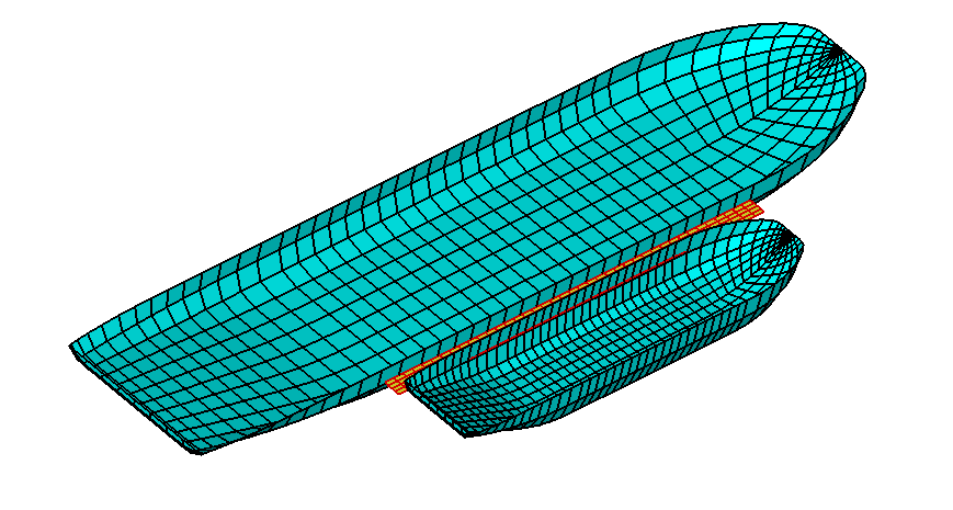
In TEST03b a dipole damper is used in the gap, at a depth of 2m below the free surface, as shown in the figure below. Except for the submergence it has the same dimensions and symmetry properties as for the lid in TEST03a, and the gdf files for the two barges are the same as in TEST03. Since it is a dipole surface its panels must be specified with the parameter NPDIPOLE in the cfg file. Except for the filename the file test03dip.dmp is the same as test03lid.gdf. Changing the value of EDAMPER in test03dip.dmp gives the results for TEST03b shown in Figure A.2.
Input file: test03b.cfg
! TEST03b.CFG -- 2 barges + dipole damper
IPLTDAT=1
NUMHDR=1
ISOLVE=1
NOOUT=0 1 1 1 0 1 1 1 1
idamper=1
npdipole(3)=(1 40)
Input file: test03b.pot
TEST03b.POT -- 2 barges + dipole damper
-1.0 HBOT
-1 1 IRAD,IDIFF
npergroup=3
-6
4.3 0.05
-40
4.6 0.01
-9
5.0 0.05
1 NBETA
270.0 BETA
3 NBODY
test03b1.gdf
0.0 -11.0 0.0 0.0
1 1 1 1 1 1
test03b2.gdf
0.0 6.0 0.0 0.0
1 1 1 1 1 1
test03dip.gdf
0.0 0.0 0.0 0.0
1 1 1 1 1 1
test03dip dipole damper in gap, depth 2m
1.000000 9.806650
1 1
40
1.250000 0.0000000E+00 -2.000000
0.0000000E+00 0.0000000E+00 -2.000000
0.0000000E+00 0.5000000 -2.000000
1.250000 0.5000000 -2.000000
2.500000 0.0000000E+00 -2.000000
1.250000 0.0000000E+00 -2.000000
Input file: test03dip.dmp
test03dip.dmp file, edamper=0.0
1 ndampers
1 40 npdamper
0.0 edamper
Input file: test03b.frc
TEST03b.FRC -- 2 barges + dipole damper
0 0 1 0 0 1 0 0 0
0.000000 VCG
1.000000 .0000000 .0000000
.0000000 1.000000 .0000000
.0000000 .0000000 1.000000 XPRDCT
0.000000 VCG
1.000000 .0000000 .0000000
.0000000 1.000000 .0000000
.0000000 .0000000 1.000000 XPRDCT
0.000000 VCG
1.000000 .0000000 .0000000
.0000000 1.000000 .0000000
.0000000 .0000000 1.000000 XPRDCT
0 NBETAH
1 NFIELD
0. 0. 0. XFIELD
A.4 BODY IN A CHANNEL OR NEAR A WALL – TEST04
The option to analyze bodies near one vertical wall, or two vertical walls which intersect at a right angle, is described in (Section 12.4). The option to analyze bodies in a channel bounded by two parallel vertical walls is described in (Section 12.7). In Test 04 a rectangular barge of length 80m, beam 20m, draft 10m is positioned with its longitudinal axis parallel to one wall, separated by a gap of 2m. In Test 04a the same barge is in a channel of width 80m and depth 20m, with its longitudinal axis 10m off-center from the axis of the channel. Incident head waves are considered, and computations are made of the surge, heave, and pitch coefficients, RAO’s, and drift force and moment in incident waves which propagate parallel to the wall or parallel to the channel axis (BETA=0).
In the GDF file one half of the barge is discretized, forward of the midship section x = 0. Both the port and starboard sides of the barge are included in the GDF file, hence the appropriate symmetry indices for this case are ISX=1, ISY=0.
The case of one wall is considered in Test 04. Since the incident waves propagate parallel to the wall this problem is identical to the ‘barge catamaran’ studied in [6], and in TEST19, when the motion in the transverse direction is not considered. The only modifications required in the latter case are (1) a lateral offset equal to the sum of the half-beam and gap must be added to the y-coordinates of the panels in the GDF file; (2) ISY=1; and (3) the forces and moments calculated for the catamaran are the total acting on both hulls. The definition of the incident-wave amplitude differs between these different problems, however, due to the convention for the wave amplitude in the presence of a wall Section 12.4. In the present case, where the incident-wave angle is zero and the waves propagate parallel to the wall, the wave system in the absence of the body is a progressive wave with total physical amplitude 2A.
It also is possible to replicate the Test 04 results with the NBODY option, specifying two independent hulls in place of the rigid constraint implied by the catamaran. The figure below shows the catamaran configuration or, equivalently, the original hull plus its image with respect to the wall.
Input file: test04.cfg
! TEST04.POT -- Barge near wall, ILOWHI=0
ilowgdf=1
ipltdat=5
ISOR=1
ISOLVE=0
ISCATT=0
ILOG=0
IRR=0
MONITR=0
NUMHDR=1
IWALLY0=1
Input file: test04.pot
TEST04.POT -- Barge near wall, ILOWHI=0
-1. HBOT
0 0 IRAD,IDIFF
3
6. 7. 8.
1
0.0
1 NBODY
test04.gdf
0. 12. 0. 0.
1 0 1 0 1 0
First 10 lines of input file: test04.gdf
TEST04.GDF -- Barge near wall, ILOWHI=0
40.00000 9.806650
1 0 ISX, ISY
640
3.920686 10.00000 -0.3806022
0.0000000E+00 10.00000 -0.3806022
0.0000000E+00 10.00000 0.0000000E+00
3.920686 10.00000 0.0000000E+00
3.920686 10.00000 -1.464466
0.0000000E+00 10.00000 -1.464466
Input file: test04.frc
TEST04.FRC -- Barge near wall, ILOWHI=0
1 1 1 1 0 0 0 0 1
3.0
20.00000 0.000000 0.000000
0.000000 5.000000 0.000000
0.000000 0.000000 20.00000
0
0
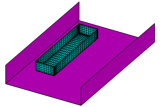
In Test 04a the mean drift force is evaluated by all three options (7,8,9). For option 7 the control surface is a pair of transverse planes across the channel, at X = 100.0. Their vertices are assigned in the file test04.csf. This file is only used for test 04a, but its filename must be the same as the gdf file. Since the data in the csf file is defined in body coordinates, the outer boundaries are offset by 10m from the global position of the channel walls in global coordinates.
The configuration of Test 04a is shown in the figure below. (Note that the tank walls and bottom extend to infinity in both directions, and only a finite segment is shown in the figure.)
! TEST04a.cfg -- Barge in channel 80x15m
ilowgdf=1
ipltdat=5
ISOR=1
ISOLVE=0
ISCATT=0
ILOG=0
IRR=0
MONITR=0
NUMHDR=1
channel_width=80.0
Input file: test04a.pot
TEST04a.POT -- Barge in channel 80x15m, off-center 10m
20. HBOT
0 0 IRAD,IDIFF
3
6. 7. 8.
1
0.0
1 NBODY
test04.gdf
0. 10. 0. 0.
1 0 1 0 1 0
TEST04a.FRC -- Barge in channel 80x15m
1 1 1 1 0 0 1 1 1
3.0
20.00000 0.000000 0.000000
0.000000 5.000000 0.000000
0.000000 0.000000 20.00000
0
0
Input file: test04.csf
test04.csf control surface for test04a in channel
1 ILOWHICSF
1 0 ISX ISY
1 0 10.0 NPATCH ICDEF PSZCSF
100.0 -50.0 -15.0
100.0 30.0 -15.0
100.0 30.0 0.0
100.0 -50.0 0.0
A.5 MULTIPLE BODIES – TEST05
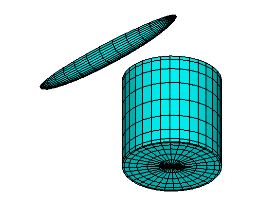
The NBODY option described in Chapter 7 is illustrated in this test run. Body one is a circular cylinder of radius 1 meter and draft 2 meters. Body 2 is a spheroid of length 4 meters and maximum radius 0.25 meters. The gap between these two bodies is set equal to the beam of the spheroid (0.5 meters) and the origin of the global coordinate system is located at the mid-point of this gap. The relative locations of the two bodies and the orientation of the spheroid are specified in the GGDF file. One quadrant of the cylinder is discretized with 112 panels. 8,6 and 8 panels are distributed in the azimuthal, radial, and vertical directions using cosine spacing in radial and vertical directions. One quadrant of the spheroid is discretized with 64 panels. 8 and 8 panels are distributed in the longitudinal, and transverse directions using cosine spacing in the longitudinal direction.
The Alternative 3 input format is used for FORCE. The separate FRC files TEST05C, TEST05S are used with IALTFRC=3. The vector IALTFRCN is included in TEST05.CFG to indicate that IALTFRC=1 in the separate FRC files for each body.
The added-mass and damping coefficients, exciting forces, motions, wave elevations, field pressures and field velocities, and drift forces are evaluated in infinite water depth for two wave periods and one wave heading.
The option is used to evaluate the mean drift force and moment using a control surface, following the instructions in Chapter 11. The control surfaces surrounding the cylinder and spheroid are defined by the input files TEST05c.csf and TEST05s.csf. In order to illustrate the alternatives, the control surface for the cylinder uses low-order panels (ILOWHICSF=0) and the control surface for the spheroid is generated with the higher-order (ILOWHICSF=1) subroutine ELLIPSOID_CS in the GEOMXACT DLL library. The corresponding output for the mean drift force and moment is contained in the file TEST05.9c. It should be noted that the higher-order control surface for the spheroid does not include the intermediate free surface patch, and thus the horizontal drift force is correct whereas the vertical drift force is not complete. The reason for omitting the free surface patch here is that the low-order solution for the body does not give a sufficiently robust evaluation of field velocities and wave elevations at points on the free surface that are very close to the body. The low-order control surface is more suitable for use with low-order body representations, in this respect, provided the panels on the free surface have dimensions similar to the dimensions of the adjacent panels on the body.
In Test05a the relative orientations of the two bodies are the same, but they are positioned such that the 90 degree rotation of the spheroid is not required, and the plane X=0 is a plane of symmetry for both bodies, as explained in Section 8.5. This reduces the number of equations (NEQN) by a factor of one-half, and reduces the run time and storage requirements. The outputs from the two runs are essentially the same, except that the directions of the coordinates are changed with corresponding changes in the definitions of the force coefficients and field velocities. A rectangular array of uniformly-spaced field points are defined on the free surface in the file test05a.frc and the parameter IFIELD_ARRAYS=1 is specified in test05a.cfg. Some of these field points are on or inside the body waterlines. These points are identified with zero in column five, in the output file test05a.fpt, and the outputs for the pressure and velocity are equal to zero at these points (see Section 4.3 and Section 4.7).
Input file: test05.cfg
! TEST05.CFG -- Cylinder + spheroid, NBODY=2, ILOWHI=0
IPLTDAT=1
ISOR=1
ILOG=0
IRR=0
NUMHDR=1
NOOUT=0 1 1 1 0 1 1 1 1
IALTFRC = 3 ! Alternative Form 3 FRC
IALTFRCN= 1 1
Input file: test05.pot
TEST05.POT -- Cylinder + spheroid, ILOWHI=0
-1.0 HBOT
0 0 IRAD,IDIFF
2
1.5 2.0
1
0.0
2 NBODY
test05c.gdf
1.25 0.0 0.0 0.0
1 1 1 1 1 1
test05s.gdf
-0.5 0.0 0.0 90.0
1 1 1 1 1 1
First 10 lines of input file: test05c.gdf
Cylinder R=1 T=2 8*(6+8)
1.000000 9.806650
1 1
112
0.0000000E+00 0.0000000E+00 -2.000000
0.0000000E+00 0.0000000E+00 -2.000000
0.2538459 5.0493091E-02 -2.000000
0.2588190 0.0000000E+00 -2.000000
0.2588190 0.0000000E+00 -2.000000
0.2538459 5.0493091E-02 -2.000000
First 10 lines of input file: test05s.gdf
Spheroid, Slendernes =0.125 Halflength=2m 8*8
2.000000 9.806650
1 1
64
2.000000 -0.0000000E+00 -0.0000000E+00
1.961571 -7.9460625E-09 -4.8772585E-02
1.961571 9.5150545E-03 -4.7835436E-02
2.000000 0.0000000E+00 -0.0000000E+00
2.000000 0.0000000E+00 -0.0000000E+00
1.961571 9.5150545E-03 -4.7835436E-02
Input file: test05.frc
TEST05.FRC -- Cylinder + spheroid, ILOWHI=0
1 1 1 1 0 3 1 1 1
1.0
test05c.frc
test05s.frc
0
1
0. 0. 0.
Input file: test05c.frc
CYL.FRC
0 0 0 0 0 0 0 0 0
0.000000
1.000000 .0000000 .0000000
.0000000 1.000000 .0000000
.0000000 .0000000 1.000000
0
0
Input file: test05s.frc
SPD.FRC
0 0 0 0 0 0 0 0 0
0.000000
1.000000 .0000000 .0000000
.0000000 1.000000 .0000000
.0000000 .0000000 1.000000
0
0
First 10 lines of input file: test05c.csf
cylinder R=1.2 T=2.2 -- low-order control surface
0 ILOWHICSF
1 1 ISX ISY
160 NPAN
0.12000E+01 0.00000E+00 0.00000E+00
0.12000E+01 0.00000E+00 -0.27500E+00
0.11769E+01 0.23411E+00 -0.27500E+00
0.11769E+01 0.23411E+00 0.00000E+00
0.11769E+01 0.23411E+00 0.00000E+00
0.11769E+01 0.23411E+00 -0.27500E+00
Input file: test05s.csf
ELLIPSOID CONTROL SURFACE defined by subroutine ELLIPSOID_CS
1 ILOWHICSF
1 1 ISX ISY
1 -1003 0.5 NPATCH IGDEF PSZCSF
2 NLINES
2.2 0.3 0.3 A, B, C
2.0 0.25 (x and y maximum of ellipsoid GDF)
! TEST05a.CFG -- array of field points
IPLTDAT=1
ISOR=1
ILOG=0
IRR=0
NUMHDR=1
NOOUT=0 1 1 1 0 1 1 1 1
IALTFRC = 3 ! Alternative Form 3 FRC
IALTFRCN= 1 1
IFIELD_ARRAYS=1
Input file: test05a.pot
TEST05a.POT -- Cylinder + spheroid, ILOWHI=0
-1.0 HBOT
0 0 IRAD,IDIFF
2 NPER
1.5 2.0 PER
1 NBETA
90.0 Beta
2 NBODY
test05c.gdf
0.0 1.25 0.0 0.0
1 1 1 1 1 1
test05s.gdf
0.0 -0.5 0.0 0.0
1 1 1 1 1 1
Input file: test05a.frc
TEST05a.FRC -- array of field points
1 1 1 1 0 3 1 1 1 (IOPTN(1-9)
1.0 (RHO -- fluid density)
test05c.frc (frc file for body 1)
test05s.frc (frc file for body 2)
0 (NBETAH)
0 (NFIELD -- no individual field points)
1 (NFIELD_ARRAYS -- number of arrays)
0 (Array is in exterior fluid domain)
11 -2.5 0.5 (NFX, X1, DELX)
10 -1.5 0.5 (NFY, Y1, DELY)
1 0.0 0.0 (NFZ, Z1, DELZ)
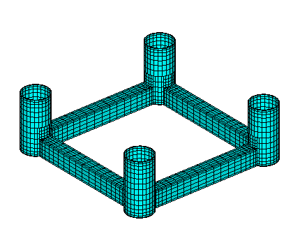
A.6 THE ISSC TENSION-LEG PLATFORM – TEST06
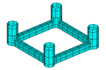
The added-mass, damping coefficients, exciting forces, motions and wave loads are evaluated for the ISSC Tension-Leg-Platform, in a finite water depth of 450 meters, for three wave periods and one wave heading. The TLP consists of four circular cylindrical columns and four rectangular pontoons as shown in the plots of the panel discretization. The radius of each column is 8.435 meters. The width and height of each pontoon are 7.5 meters and 10.5 meters, respectively. The distance between the centers of adjacent columns is 86.25 meters. Further information is given by Eatock Taylor and Jefferys [7].
Two planes of symmetry are used with 128 panels in one quadrant. Thus there are a total of 512 panels on the complete surface. The origin of the coordinate system is located at the intersection of the undisturbed free surface and the two planes of symmetry. The characteristic length is set equal to 43.125 meters, which corresponds to half of the distance between the centers of adjacent columns.
Only head seas are considered, with β = 0 specified in the .pot file. For this reason, only the modes (surge, heave, pitch) are analyzed with IRAD=IDIFF=0, and these modes are specified on line 3. There is a warning message for options 5-9, as explained in Section 10.1, since IDIFF=0.
In the .frc file the horizontal modes (1,2,6) are free and the vertical modes (3,4,5) are fixed, to represent a TLP moored by vertical tendons. The Alternative 1 form is used, with the result that the body mass is evaluated as if the TLP is freely floating (see Section 3.5).
The output shows the conventional response amplitude operator for surge, and the wave loads for heave and pitch.
Input file: test06.cfg
! TEST06.CFG -- ISSC TLP, coarse discretization
ipltdat=1
ISOR=1
ISOLVE=4
ISCATT=1
ILOG=0
IRR=0
MONITR=0
NUMHDR=1
IALTFRC=2
Input file: test06.pot
TEST06.POT -- ISSC TLP, coarse discretization
450. HBOT
0 0 IRAD,IDIFF
3
5. 10. 15.
1
0.
1 NBODY
test06.gdf
0. 0. 0. 0.
1 0 1 0 1 0
First 10 lines of input file: test06.gdf
TEST06.GDF -- ISSC TLP, coarse discretization
43.125 9.80665
1 1
128
49.09267 37.15733 0.00000
49.09267 37.15733 -5.12567
51.56456 43.12500 -5.12567
51.56456 43.12500 0.00000
49.09267 37.15733 -5.12567
49.09267 37.15733 -17.50013
Input file: test06.frc
TEST07.FRC ISSC TLP -- ILOWHI=0, fine discretization -- IALTFRC=2
1 1 1 -2 0 0 0 1 1 IOPTN (IOPTN(4)<0 signifies fixed modes)
6 NDFR
1 1 0 0 0 1 IMODE
1. RHO
0. 0. 3.0 XCG
1 IMASS
53066.4 0. 0. 0. 159199.2 0.
0. 53066.4 0. -159199.2 0. 0.
0. 0. 53066.4 0. 0. 0.
0. -159199.2 0. 8.0201552E7 0. 0.
159199.2 0. 0. 0. 8.0201552E7 0.
0. 0. 0. 0. 0. 9.54906731E7
0 IDAMP
0 ISTIFF
0 NBETAH
0 NFIELD
TEST06a is intended to refine the analysis of the ISSC TLP described in TEST06. 1012 panels are used on each quadrant, resulting in 4048 panels for the complete structure. The block iterative solver is used (ISOLVE=4) to provide a relatively fast but robust solution. For the sake of variety in the analysis of the diffraction problem, the solution for the scattered potential is computed (ISCATT=1).
Alternative form 2 of .FRC is used, but the mass is assumed to be equal to the displacement computed by WAMIT. Note that the displacement is about 4% greater than for Test Run 2, due to the more accurate description of the columns. (The panel vertices are defined to lie on the exact circular cylinder surface, hence the flat panels define a surface with less displaced volume than the exact body.)
Comparisons should be made with the output files from TEST06 to judge the convergence of the results with increasing numbers of panels. As in TEST06 a warning message is displayed for Options 8 and 9 since IDIFF=0.
Input file: test06a.cfg
! TEST06a.CFG ISSC TLP -- ILOWHI=0, fine discretization
ipltdat=1
ISOR=1
ISOLVE=4
ISCATT=1
ILOG=1
IRR=0
MONITR=0
NUMHDR=1
IALTFRC=2
Input file: test06a.pot
TEST06a.POT ISSC TLP -- ILOWHI=0, fine discretization
450. HBOT
0 0 IRAD,IDIFF
3
5. 10. 15.
1
0.
1 NBODY
test06a.gdf
0. 0. 0. 0.
1 0 1 0 1 0
First 10 lines of input file: test06a.gdf
TEST06a.GDF ISSC TLP -- ILOWHI=0, fine discretization
43.125 9.806650
1 1
1012
49.09267 37.15733 0.00000
49.09267 37.15733 -0.33626
50.43388 38.90522 -0.33626
50.43388 38.90522 0.00000
49.09267 37.15733 -0.33626
49.09267 37.15733 -1.33212
Input file: test06a.frc
TEST06a.FRC ISSC TLP -- ILOWHI=0, fine discretization -- IALTFRC=2
1 1 1 -2 0 0 0 1 1 IOPTN (IOPTN(4)<0 signifies fixed modes)
6 NDFR
1 1 0 0 0 1 IMODE
1. RHO
0. 0. 3.0 XCG
1 IMASS
53066.4 0. 0. 0. 159199.2 0.
0. 53066.4 0. -159199.2 0. 0.
0. 0. 53066.4 0. 0. 0.
0. -159199.2 0. 8.0201552E7 0. 0.
159199.2 0. 0. 0. 8.0201552E7 0.
0. 0. 0. 0. 0. 9.54906731E7
0 IDAMP
0 ISTIFF
0 NBETAH
0 NFIELD
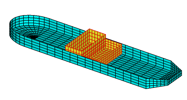
A.7 FPSO WITH TWO INTERNAL TANKS – TEST07
The vessel shown below has a length of 200m, beam 44m, and draft 12m, with the same hull form as in Test22. The internal rectangular tanks have widths 42m and lengths 20m. The aft side of tank 1 and forward side of tank 2 are in the plane x=0. The forward tank is filled to a depth of 16m and the aft tank to 11m, with free surfaces in both tanks. The fluid in the tanks has a relative density of 1.0 as specified in the file test07.cfg.
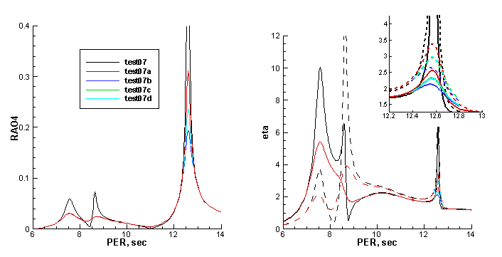
The motions in the tanks and their interaction with the vessel’s motion are analyzed using the method described in Section 12.1. Special attention is given to the resonant roll motion and the first sloshing mode of the tanks. A large number of closely-spaced wave periods are input in test07.pot to define these resonances, using the parameter NPERGROUP. Beam seas are considered, with β = 90∘. The tank panels and densities are input in the cfg file, as well as the parameter ITANKFPT which specifies that field points in the frc file are in the tanks. These field points are assigned to evaluate the free surface elevations shown in Fig A.3, at the points on the free surface of each tank x = 10m, y = 20m, 1m from the tank walls.
Input file: test07.cfg
! TEST07.CFG fpso with 2 tanks + lids
ILOWHI=0
ILOG=1
ISOLVE=1
MONITR=0
NUMHDR=1
NOOUT= 1 1 1 1 0 1 1 1 1
NPTANK=(309-416) (417-524)
RHOTANK= 1.0 1.0 (relative densities of tank fluids)
ITANKFPT=1 (tank field points are in .frc file)
IPLTDAT=1
TEST07.POT fpso with 2 tanks
-1.0
1 1 IRAD, IDIFF
npergroup=5
-15
6.0 0.1
-75
7.5 .02
-31
9.0 0.1
-28
12.2 .02
-13
12.8 0.1
1 NBETA (array BETA follows)
90.
1 NBODY
test07.gdf
0. 0.0 0. 0. XBODY
0 0 0 0 0 0 IMODE(1-6)
First 10 lines of input file: test07.gdf
TEST07.GDF -- fpso with 2 tanks
1.000000 9.806650
0 1
524
99.42356 4.291987 -12.00000
100.0000 0.0000000E+00 -12.00000
95.00000 0.0000000E+00 -12.00000
94.51963 3.576655 -12.00000
97.71638 8.419035 -12.00000
99.42356 4.291987 -12.00000
Input file: test07.frc
TEST07.FRC fpso with 2 tanks
1 1 1 1 0 1 0 0 0
0.000000 VCG
10.000000 .0000000 .0000000
.0000000 10.000000 .0000000
.0000000 .0000000 10.000000 XPRDCT
0 NBETAH
2 NFIELD
1 10.0 20.0 5.0
2 -10.0 20.0 0.0
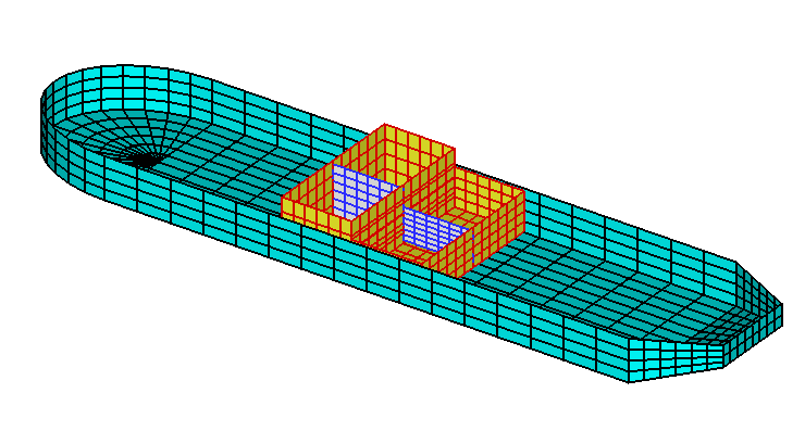
In test07a,b,c,d vertical dipole dampers are placed in the center of each tank, as shown in the figure below. Each damper is represented by 36 panels, which extend between the two transverse walls on the centerline y = 0, and vertically from 1m above the tank bottom to 1m below the free surface. (It is necessary to include at least one of these gaps, so that the same fluid domain exists in the entire tank.) The sloshing modes associated with sway and roll are antisymmetric about y=0, with maximum transverse velocities at y=0. Thus this is the most effective location for vertical dampers. The parameter NPDIPOLE identifies the corresponding panels as dipole panels.
In test07a the parameter IDAMPER=1 is included in the cfg file as explained in Section 12.8. The file test07a.dmp identifies the panels for each damper and the damping coefficients EDAMPER=1.0. The outputs are shown by the red lines in Figure A.3, with the damping most evident for the sloshing modes near 6sec, and to a lesser extent for roll near 12.6sec. If EDAMPER=0.0 is assigned in the dmp file the results in Figure A.3 are practically identical to those for test07.
In test07b external roll damping is added in the file test07b.frc, in addition to the dipole tank dampers in test07a. Since this is the only change, it is not necessary to re-run poten, and IPOTEN=0 is assigned in test07b.cfg. The outputs from test07b are shown by the blue lines in Figure A.3.
In test07c the parameter IDAMPER=2 is included in the cfg file as explained in Section 12.8. Thus the dipole dampers are fixed relative to the tank, and the pressure forces on the dampers are transmitted directly to the vessel. In this case it is necessary to re-run poten, but the same gdf, spl and dmp files can be used as in tests 07a and 07b. Thus test07a.gdf is listed in the test07c.pot file. The outputs from test07c are shown by the green lines in Figure A.3.
In test07d the parameter IDAMPER=3 is used. Thus the dipole dampers are free relative to the tank, but the relative velocity including the rigid-body motions is used in the boundary condition on the dampers as explained in Section 12.8. The outputs are shown by the light blue lines in Figure A.3.
Input file: test07a.cfg
! TEST07a.CFG fpso with 2 tanks + dipole dampers
ILOWHI=0
ILOG=1
ISOLVE=1
MONITR=0
NUMHDR=1
NOOUT= 1 1 1 1 0 1 1 1 1
NPTANK=(309-452) (453-596)
NPDIPOLE= (417-452) (561-596)
RHOTANK= 1.0 1.0 (relative densities of tank fluids)
IDAMPER=1
IPLTDAT=1
ITANKFPT=1 (tank field points are in .frc file)
Input file: test07a.pot
test07a.pot fpso with 2 interior tanks + dipole dampers
-1.0
1 1 IRAD, IDIFF
npergroup=5
-15
6.0 0.1
-75
7.5 .02
-31
9.0 0.1
-28
12.2 .02
-13
12.8 0.1
1 NBETA (array BETA follows)
90.
1 NBODY
test07a.gdf
0.0 0.0 0.0 0.0 XBODY
1 1 1 1 1 1 IMODE(1-6)
TEST07a.GDF -- fpso with 2 tanks + dampers
1.000000 9.806650
0 1
596
99.42356 4.291987 -12.00000
100.0000 0.0000000E+00 -12.00000
95.00000 0.0000000E+00 -12.00000
94.51963 3.576655 -12.00000
97.71638 8.419035 -12.00000
99.42356 4.291987 -12.00000
Input file: test07a.dmp
test07a.dmp file, edamper=1.0
2 ndampers
417 452 npdamper
1.0 edamper
561 596 npdamper
1.0 edamper
Input file: test07a.frc
TEST07a.FRC fpso with 2 tanks + dipole dampers
1 0 1 2 0 1 0 0 0
0.000000 VCG
10.000000 .0000000 .0000000
.0000000 10.000000 .0000000
.0000000 .0000000 10.000000 XPRDCT
0 NBETAH
2 NFIELD
1 10.0 20.0 5.0
2 -10.0 20.0 0.0
Input file: test07b.cfg
! TEST07b.CFG fpso with 2 tanks + dipole dampers, IALTFRC=2
ILOWHI=0
ILOG=1
ISOLVE=1
MONITR=0
NUMHDR=1
NOOUT= 1 1 1 1 0 1 1 1 1
NPTANK=(309-452) (453-596)
NPDIPOLE= (417-452) (561-596)
RHOTANK= 1.0 1.0 (relative densities of tank fluids)
IDAMPER=1
IPLTDAT=1
ITANKFPT=1 (tank field points are in .frc file)
IALTFRC=2
IPOTEN=0
Input file: test07b.frc
TEST07b.FRC fpso with external roll damping EXDAMP=1E5, IALTFRC=2
1 0 1 2 0 1 0 0 0
1. RHO
0.0 0.0 0.0 XCG,YCG,ZCG
1 IMASS
75200.9 0.0 0.0 0.0 0.0 0.0
0.0 75200.9 0.0 0.0 0.0 28065.7
0.0 0.0 75200.9 0.0 -28065.7 0.0
0.0 0.0 0.0 7520092.0 0.0 0.0
0.0 0.0 -28065.7 0.0 7520092.0 0.0
0.0 28065.7 0.0 0.0 0.0 7520092.0
1 IDAMP
0.0 0.0 0.0 0.0 0.0 0.0
0.0 0.0 0.0 0.0 0.0 0.0
0.0 0.0 0.0 0.0 0.0 0.0
0.0 0.0 0.0 100000.0 0.0 0.0
0.0 0.0 0.0 0.0 0.0 0.0
0.0 0.0 0.0 0.0 0.0 0.0
0 ISTIFF
0 NBETAH
2 NFIELD
1 10.0 20.0 5.0
2 -10.0 20.0 0.0
Input file: test07c.cfg
! TEST07c.CFG fpso with 2 tanks + fixed dipole dampers
ILOWHI=0
ILOG=1
ISOLVE=1
MONITR=0
NUMHDR=1
NOOUT= 1 1 1 1 0 1 1 1 1
NPTANK=(309-452) (453-596)
NPDIPOLE= (417-452) (561-596)
RHOTANK= 1.0 1.0 (relative densities of tank fluids)
IDAMPER=2
IPLTDAT=1
ITANKFPT=1 (tank field points are in .frc file)
Input file: test07c.pot
test07c.pot fpso with 2 interior tanks + fixed dipole dampers
-1.0
1 1 IRAD, IDIFF
npergroup=5
-15
6.0 0.1
-75
7.5 .02
-31
9.0 0.1
-28
12.2 .02
-13
12.8 0.1
1 NBETA (array BETA follows)
90.
1 NBODY
test07a.gdf
0.0 0.0 0.0 0.0 XBODY
1 1 1 1 1 1 IMODE(1-6)
Input file: test07c.frc
TEST07c.FRC fpso with 2 tanks + fixed dipole dampers
1 0 1 2 0 1 0 0 0
0.000000 VCG
10.000000 .0000000 .0000000
.0000000 10.000000 .0000000
.0000000 .0000000 10.000000 XPRDCT
0 NBETAH
2 NFIELD
1 10.0 20.0 5.0
2 -10.0 20.0 0.0
Input file: test07d.cfg
! TEST07d.CFG fpso with 2 tanks + free dipole dampers
ILOWHI=0
ILOG=1
ISOLVE=1
MONITR=0
NUMHDR=1
NOOUT= 1 1 1 1 0 1 1 1 1
NPTANK=(309-452) (453-596)
NPDIPOLE= (417-452) (561-596)
RHOTANK= 1.0 1.0 (relative densities of tank fluids)
IDAMPER=3
IPLTDAT=1
ITANKFPT=1 (tank field points are in .frc file)
Input file: test07d.pot
test07d.pot fpso with 2 interior tanks + free dipole dampers
-1.0
1 1 IRAD, IDIFF
npergroup=5
-15
6.0 0.1
-75
7.5 .02
-31
9.0 0.1
-28
12.2 .02
-13
12.8 0.1
1 NBETA (array BETA follows)
90.
1 NBODY
test07a.gdf
0.0 0.0 0.0 0.0 XBODY
1 1 1 1 1 1 IMODE(1-6)
Input file: test07d.frc
TEST07d.FRC fpso with 2 tanks + fixed dipole dampers
1 0 1 2 0 1 0 0 0
0.000000 VCG
10.000000 .0000000 .0000000
.0000000 10.000000 .0000000
.0000000 .0000000 10.000000 XPRDCT
0 NBETAH
2 NFIELD
1 10.0 20.0 5.0
2 -10.0 20.0 0.0
A.8 ELASTIC COLUMN WITH GENERALIZED MODES – TEST08
This test run evaluates the force coefficients and RAO’s for a bottom-mounted vertical cylinder of circular cross-section, with four bending modes defined by shifted Jacobi polynomials. The hydroelastic analysis of these bending modes is analyzed using the generalized body mode option described in Chapter 8. Further details are given in Reference [13]. The cylinder extends from the free surface, where it is free, down to the bottom, at a depth of 200m, where it is clamped. The cylinder radius is 10m. Since the cylinder is clamped at the bottom the six rigid-body modes are all fixed, and specified by the values MODE(j)=0 in the POT file.
External mass and stiffness matrices are defined in the (Alternative 2) FRC file. The cylinder is considered to have a constant distributed mass equal to half of the displaced mass of fluid, and also a concentrated mass at the free surface equal to the displaced mass. The stiffness factor EI for the beam equation is assumed constant with the value 0.41m0h3, where m 0 is the concentrated mass and h is the fluid depth. No matrix elements are required for the square submatrix (i,j) ≤ 6 since the body is fixed in these modes. Further details for this case are given in [13].
The cylinder geometry is defined with two planes of symmetry and 512 panels on one quadrant. The length scale ULEN is specified as 1.0 to simplify the definitions of modes and output quantities. The generalized modes are defined in the subroutine defmod.f, which is distributed to licensed users. The use of DEFMOD is described in Chapter 8. The output file from DEFMOD, TEST08.MOD, is included with the test files so that this test can be run without prior use of DEFMOD. Only one wave period is considered here, which coincides with resonant bending motion of the cylinder. See also TEST18, where the NEWMODES DLL file is used to define the generalized modes.
Input file: test08.cfg
! TEST08.CFG -- bending of vertical column with 4 generalized modes
ilowgdf=1
ipltdat=5
NUMHDR=1
NUMNAM=0
ISOR=0
IRR=0
MONITR=0
NEWMDS=4
IALTFRC=2
Input file: test08.pot
TEST08.POT -- bending of vertical column at resonance, 200m depth
200.0 HBOT
0 0 IRAD,IDIFF
1
6.5
1
0.0
1 NBODY
test08.gdf
0.0 0.0 0.0 0.0
0 0 0 0 0 0
First 10 lines of input file: test08.gdf
TEST08.GDF vertical cylinder, 16*32, cosine spacing at free surface
1.0000 9.80665
1 1
512
10.0000 0.000000 -200.000
9.95185 0.980171 -200.000
9.95185 0.980171 -190.186
10.0000 0.000000 -190.186
10.0000 0.000000 -190.186
9.95185 0.980171 -190.186
Input file: test08.frc
TEST08.FRC file, vertical column with 4 bending modes
1 1 1 1 0 0 0 0 0
1.0
.0000000 .0000000 1.000000
1
0. 0. 0. 0. 0. 0. 0. 0. 0. 0.
0. 0. 0. 0. 0. 0. 0. 0. 0. 0.
0. 0. 0. 0. 0. 0. 0. 0. 0. 0.
0. 0. 0. 0. 0. 0. 0. 0. 0. 0.
0. 0. 0. 0. 0. 0. 0. 0. 0. 0.
0. 0. 0. 0. 0. 0. 0. 0. 0. 0.
0. 0. 0. 0. 0. 0. 69115. 62832. 62832. 62832.
0. 0. 0. 0. 0. 0. 62832. 67320. 62832. 62832.
0. 0. 0. 0. 0. 0. 62832. 62832. 66323. 62832.
0. 0. 0. 0. 0. 0. 62832. 62832. 62832. 65688.
0
1
0. 0. 0. 0. 0. 0. 0. 0. 0. 0.
0. 0. 0. 0. 0. 0. 0. 0. 0. 0.
0. 0. 0. 0. 0. 0. 0. 0. 0. 0.
0. 0. 0. 0. 0. 0. 0. 0. 0. 0.
0. 0. 0. 0. 0. 0. 0. 0. 0. 0.
0. 0. 0. 0. 0. 0. 0. 0. 0. 0.
0. 0. 0. 0. 0. 0. 103044. 412177. 824354. 1339575.
0. 0. 0. 0. 0. 0. 412177. 4430902. 9789203. 16487078.
0. 0. 0. 0. 0. 0. 824354. 9789203. 37899671. 64382041.
0. 0. 0. 0. 0. 0. 1339575. 16487078. 64382041. 162406554.
0
0
A.9 SPAR WITH THREE STRAKES – TEST09
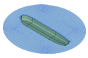
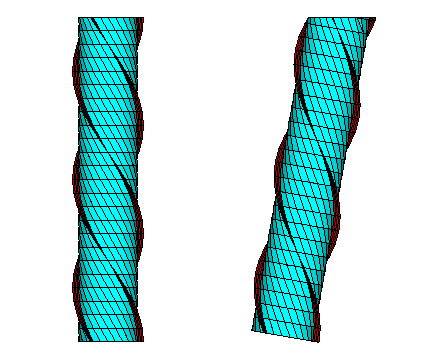
This test run analyzes a circular cylinder with three spiral strakes. The strakes are modeled as zero-thickness dipole panels, following the method described in Section 5.4. The radius of the cylinder is 18m and the draft is 200m. The strake width is 3.7m. There are no planes of symmetry, due to the twist of the strakes. A total of 960 panels are used, including 672 on the cylinder plus 288 on the strakes. The excerpts from the GDF file include the first body panel and also the first dipole panel.
In TEST09A the trimmed waterline option is used, with the parameters ITRIMWL and XTRIM specified in the file TEST09A.CFG. These parameters specify a vertical trim of 10m and a pitch angle of 10 degrees. The same TEST09.GDF file is used for both tests. Only the filenames are changed in TEST09A.POT and TEST09A.FRC. Perspective views in the untrimmed and trimmed conditions are shown below.
The FORCE run includes all options which can be evaluated without using the source formulation (ISOR=1), since the latter option cannot be used with dipole panels. The body pressure file TEST09.5p includes the pressure on the body panels, and the pressure jump on the dipole panels. The corresponding panel centroids are listed in the output file TEST09.PNL.
The figure below shows the submerged body surfaces for both TEST09 and TEST09a. The dipole panels are red.
Input file: test09.cfg
! TEST09.CFG (Spar with three strakes)
ilowgdf=1
ipltdat=5
ISOR=0
ISOLVE=0
ISCATT=1
ILOG=0
IRR=0
MONITR=0
NUMHDR=1
IPERIN=3
IPEROUT=3
NOOUT= 1 1 1 1 0 1 1 1 1
NPDIPOLE = ( 673 960 )
Input file: test09.pot
TEST09.POT (Spar with three strakes)
-1. HBOT
1 1 IRAD,IDIFF
3 NPER (array PER follows)
0.1 0.5 1.0
2 NBETA (array BETA follows)
0.0 45. (end of file)
1 NBODY
test09.gdf
0. 0. 0. 0. HBOT, XBODY(1-4)
1 1 1 1 1 1 IMODE(1-6)
First 10 lines of input file: test09.gdf
SPAR R, D, W, T, NS, TWIST= 18.00 200.00 3.70 0.000000 3 1.000
18.00000 9.806650
0 0
960
18.00000 0.0000000E+00 0.0000000E+00
17.38667 4.658743 -8.333333
15.58846 9.000000 -8.333333
17.38667 4.658743 0.0000000E+00
17.38667 4.658743 -8.333333
15.58846 9.000000 -16.66667
Input file: test09.frc
TEST09.FRC (Spar with three strakes)
1 1 1 1 1 3 0 2 0
0.000000 VCG
1.000000 .0000000 .0000000
.0000000 1.000000 .0000000
.0000000 .0000000 1.000000 XPRDCT
0 NBETAH
2 NFIELD
23. 0. 0.
15. 15. -0.5 (end of file)
Input file: test09a.cfg
! TEST09a.CFG -- Spar with trimmed waterline
ISOLVE=0
ISCATT=1
ILOG=0
IRR=0
MONITR=0
NUMHDR=1
IPERIN=3
IPEROUT=3
NOOUT= 1 1 1 1 0 1 1 1 1
ITRIMWL=1
XTRIM=10. 10. 0.
NPDIPOLE = ( 673 960 )
Input file: test09a.pot
TEST09A.POT -- spar - trimmed waterline
-1. HBOT
1 1 IRAD,IDIFF
3 NPER (array PER follows)
0.1 0.5 1.0
2 NBETA (array BETA follows)
0.0 45. (end of file)
1 NBODY
test09.gdf
0. 0. 0. 0. HBOT, XBODY(1-4)
1 1 1 1 1 1 IMODE(1-6)
Input file: test09a.frc
TEST09A.FRC (Spar with three strakes, trimmed waterline)
1 1 1 1 1 3 0 2 0
0.000000 VCG
1.000000 .0000000 .0000000
.0000000 1.000000 .0000000
.0000000 .0000000 1.000000 XPRDCT
0 NBETAH
2 NFIELD
23. 0. 0.
15. 15. -0.5 (end of file)
A.11 CIRCULAR CYLINDER – TEST11
The same cylinder used for the low-order TEST01 is used here with the higher-order option (ILOWHI=1). Two alternatives are used for the geometry.
In TEST11 the geometry is defined by B-splines (IGDEF=1). The parameters, knot vectors, and coefficients for each patch are contained in the file TEST11.GDF. It should be noted that the circular patches and boundaries cannot be fit exactly with B-splines; however the geometric errors are generally much smaller in this case, compared to the flat-panel representation in TEST01. For example the maximum error of any point output in the data file test11.pnl is less than 3E-5, and the maximum error in the computed volume is 1E-5. By comparison, using the flat-panel discretization in TEST01, the maximum error in the computed volume is 3E-3. Thus, when the higher-order method is used, the principal errors in the results should be associated with the approximation of the potential by B-splines, as opposed to the representation of the geometry. This approximation can be systematically refined by increasing the number of panels, or by using the PANEL-SIZE option in the CONFIG.WAM (or CFG) file and reducing the value of this parameter.
In TEST11a the geometry is defined analytically by the GEOMXACT.F subroutine CIRCCYL (IGDEF=-1). The radius and draft of the cylinder are input in TEST11a.GDF. The parameter INONUMAP=0 specifies uniform mapping. Comparison of the output files with TEST01 and TEST11 confirms the statements above regarding accuracy. Most of the output data from TEST11 and TEST11a agree to at least five decimals, except for the third wave period which coincides with an irregular frequency.
In TEST11b the geometry is defined analytically, in the same manner as for TEST11a, except that nonuniform mapping is specified by the parameter INONUMAP=1 as explained in Section 6.8. This modification gives a more accurate solution near the corner and waterline, which is particularly beneficial for the pressure drift force evaluation. Comparison between the outputs for the momentum and pressure drift force shows that the results are more consistent in this case, compared to the use of uniform mapping in TEST11a. More extensive comparisons for the same geometry are included in Reference 24.
TEST11c illustrates the use of the option IGDEF=2, where the geometry is described by MultiSurf (see Section 6.7 and Appendix 2). In this case the same nonuniform mapping is used as in TEST11b, using the relabeling technique in MultiSurf. Comparison of the results with TEST11b indicates that they are practically identical.
Input file: test11.cfg
! TEST11.CFG Cylinder R=1, T=0.5, igdef=1
ipltdat=5
ilowgdf=5
ILOWHI=1
IRR=0
ISOLVE=2
KSPLIN=3
IQUADO=3
IQUADI=4
MONITR=0
NOOUT= 1 1 1 1 0 1 1 1 1
NUMHDR=1
Input file: test11.pot
TEST11.POT Cylinder R=1, T=0.5, igdef=1
-1.
1 1 IRAD, IDIFF
3 NPER (array PER follows)
8.971402 2.006403 1.003033
1 NBETA (array BETA follows)
0.
1 NBODY
test11.gdf
0. 0. 0. 0. XBODY
1 1 1 1 1 1 IMODE(1-6)
First 10 lines of input file: test11.gdf
TEST11 cylinder R=1 T=0.5 defined by B-splines (IGDEF=1)
1. 9.80665 ULEN GRAV
1 1 ISX ISY
2 1 NPATCH, IGDEF
4 2
4 4
-1.00000000000000 -1.00000000000000 -1.00000000000000
-1.00000000000000 -0.500000000000000 0.000000000000000E+000
0.500000000000000 1.00000000000000 1.00000000000000
1.00000000000000 1.00000000000000
Input file: test11.spl
TEST11 cylinder R=1 T=0.5 defined by B-splines (IGDEF=1)
4 2 NU NV (Patch 1, side u azimuthal v vertical)
4 2 NU NV (Parch 2, bottom u azimuthal v radial)
Input file: test11.frc
TEST11.FRC Cylinder R=1, T=0.5, igdef=1
1 1 1 1 3 3 0 2 2
0.000000 VCG
1.000000 .0000000 .0000000
.0000000 1.000000 .0000000
.0000000 .0000000 1.000000 XPRDCT
0 NBETAH
2 NFIELD
1.5 0. 0.
1.5 0. -0.5 (end of file)
Input file: test11a.cfg
! TEST11a.CFG Cylinder R=1, T=0.5, igdef=-1
ipltdat=5
ILOWHI=1
IRR=0
ISOLVE=2
KSPLIN=3
IQUADO=3
IQUADI=4
MONITR=0
NUMHDR=1
NOOUT= 1 1 1 1 0 1 1 1 1
Input file: test11a.pot
TEST11A.POT Cylinder R=1, T=0.5, igdef=-1
-1.
1 1 IRAD, IDIFF
2 NPER (array PER follows)
8.971402 2.006403
1 NBETA (array BETA follows)
0.
1 NBODY
test11a.gdf
0. 0. 0. 0. XBODY
1 1 1 1 1 1 IMODE(1-6)
Input file: test11a.gdf
TEST11a cylinder R=1 T=0.5 -- analytic geometry (npatch=2)
1. 9.80665 ULEN GRAV
1 1 ISX ISY
2 -1 NPATCH IGDEF
2
1.0 0.5 RADIUS, DRAFT
0 UNIFORM MAPPING
Input file: test11a.spl
TEST11a.spl - cylinder R=1 T=0.5 -- analytic geometry (npatch=2)
4 2 NU NV (Patch 1, side u azimuthal v vertical)
4 2 NU NV (Parch 2, bottom u azimuthal v radial)
Input file: test11a.frc
TEST11a.FRC Cylinder R=1, T=0.5, igdef=-1
1 1 1 1 3 3 0 2 2
0.000000 VCG
1.000000 .0000000 .0000000
.0000000 1.000000 .0000000
.0000000 .0000000 1.000000 XPRDCT
0 NBETAH
2 NFIELD
1.5 0. 0.
1.5 0. -0.5 (end of file)
Input file: test11b.cfg
! TEST11b.CFG Cylinder R=1, T=0.5, igdef=1
ILOWHI=1
IRR=0
ISOLVE=2
KSPLIN=3
IQUADO=3
IQUADI=4
MONITR=0
NUMHDR=1
NOOUT= 1 1 1 1 0 1 1 1 1
Input file: test11b.pot
TEST11B.POT Cylinder R=1, T=0.5, igdef=-1
-1.
1 1 IRAD, IDIFF
2 NPER (array PER follows)
8.971402 2.006403
2 NBETA (array BETA follows)
0. 45.
1 NBODY
test11b.gdf
0. 0. 0. 0. XBODY
1 1 1 1 1 1 IMODE(1-6)
Input file: test11b.gdf
TEST11 cylinder R=1 T=0.5 -- analytic geometry, nonuniform mapping
1. 9.80665 ULEN GRAV
1 1 ISX ISY
2 -1 NPATCH IGDEF
2 NLINES
1.0 0.5 RADIUS, DRAFT
1 INONUMAP (nonuniform mapping)
Input file: test11b.spl
TEST11b.spl - cylinder R=1 T=0.5 -- analytic geometry (npatch=2)
4 2 NU NV (Patch 1, side u azimuthal v vertical)
4 2 NU NV (Parch 2, bottom u azimuthal v radial)
Input file: test11b.frc
TEST11B.FRC Cylinder R=1, T=0.5, igdef=-1
1 1 1 1 3 3 0 2 2
0.000000 VCG
1.000000 .0000000 .0000000
.0000000 1.000000 .0000000
.0000000 .0000000 1.000000 XPRDCT
0 NBETAH
2 NFIELD
1.5 0. 0.
1.5 0. -0.5 (end of file)
Input file: test11c.cfg
! TEST11c.CFG Cylinder R=1, T=0.5, igdef=2
ILOWHI=1
IRR=0
ISOLVE=2
KSPLIN=3
IQUADO=3
IQUADI=4
MONITR=0
NUMHDR=1
NOOUT= 1 1 1 1 0 1 1 1 1
Input file: test11c.pot
TEST11C.POT Cylinder R=1, T=0.5, igdef=2
-1.
1 1 IRAD, IDIFF
2 NPER (array PER follows)
8.971402 2.006403
2 NBETA (array BETA follows)
0. 45.
1 NBODY
test11c.gdf
0. 0. 0. 0. XBODY
1 1 1 1 1 1 IMODE(1-6)
Input file: test11c.gdf
TEST11 cylinder R=1 T=0.5 -- MultiSurf .ms2 input, nonuniform mapping
1. 9.80665 ULEN GRAV
1 1 ISX ISY
0 2 NPATCH IGDEF
3 NLINES
TEST11C.MS2
wetted_surfs
0 0 0 default settings: FAST, DivMult, outward normal
Input file: test11c.spl
TEST11c.spl - cylinder R=1 T=0.5 -- MultiSurf geometry (npatch=2)
4 2 NU NV (Patch 1, side u azimuthal v vertical)
4 2 NU NV (Parch 2, bottom u azimuthal v radial)
Input file: test11c.frc
TEST11C.FRC Cylinder R=1, T=0.5, igdef=2
1 1 1 1 3 3 0 2 2
0.000000 VCG
1.000000 .0000000 .0000000
.0000000 1.000000 .0000000
.0000000 .0000000 1.000000 XPRDCT
0 NBETAH
2 NFIELD
1.5 0. 0.
1.5 0. -0.5 (end of file)
A.12 IRREGULAR-FREQUENCY REMOVAL – TEST12
TEST12 is the higher-order analog of TEST02, intended to illustrate the removal of irregular-frequency effects using the higher-order method. As in TEST11a, the geometry is defined analytically (IGDEF=-1) and the dimensions are input in the file TEST12.GDF. In this case NPATCH=3 is specified, where the additional patch corresponds to the interior free surface as required for the irregular-frequency option. In the figures below the patch and panels on the interior free surface are shaded red. One quadrant of the side and interior free surface are omitted to show the bottom surface.
Input file: test12.cfg
! TEST12.CFG Cylinder R=1, T=0.5, igdef=-1, npatch=3 (IRR=1)
ILOWHI=1
IRR=1
ILOG=1
ISOLVE=1
KSPLIN=3
IQUADO=3
IQUADI=4
MONITR=0
NUMHDR=1
NOOUT= 1 1 1 1 0 1 1 1 1
Input file: test12.pot
TEST12.POT Cylinder R=1, T=0.5, igdef=-1, npatch=3 (IRR=1)
-1.
1 1 IRAD, IDIFF
3 NPER (array PER follows)
8.971402 2.006403 1.003033
2 NBETA (array BETA follows)
0. 45.
1 NBODY
test12.gdf
0. 0. 0. 0. XBODY
1 1 1 1 1 1 IMODE(1-6)
Input file: test12.gdf
TEST12 cylinder R=1 T=0.5 -- analytic geometry (npatch=3)
1. 9.80665 ULEN GRAV
1 1 ISX ISY
3 -1 NPATCH IGDEF
2 NLINES
1.0 0.5 RADIUS, DRAFT
0 UNIFORM MAPPING
Input file: test12.spl
TEST12.spl - cylinder R=1 T=0.5 -- analytic geometry (npatch=3)
4 2 NU NV (Patch 1, side u azimuthal v vertical)
4 2 NU NV (Parch 2, bottom u azimuthal v radial)
4 4 NU NV (Parch 3, interior free surface) RESET NV=2 FOR STANDARD
Input file: test12.frc
TEST12.FRC Cylinder R=1, T=0.5, igdef=-1 (irr=1)
1 1 1 1 3 3 0 2 2
0.000000 VCG
1.000000 .0000000 .0000000
.0000000 1.000000 .0000000
.0000000 .0000000 1.000000 XPRDCT
0 NBETAH
2 NFIELD
1.5 0. 0.
1.5 0. -0.5 (end of file)
A.13 MULTIPLE BODIES – TEST13
This test uses the same cylinder and spheroid as in the low-order TEST05. The geometry is defined by the input files TEST13C.GDF and TEST13S.GDF. TEST13C uses IGDEF=-1 as in TEST11a. TEST13S.GDF uses the ELLIPSOID subroutine (IGDEF=-4) with the semi-axes (2.0, 0.25, 0.25) specified. The same separate FRC files TEST05C, TEST05S are used with IALTFRC=3. The vector IALTFRCN is included in TEST13.CFG to indicate that IALTFRC=1 in the separate FRC files for each body. (Normally it is necessary to duplicate the FRC files for analogous runs, as for example in TEST01 and TEST11, since the output filenames are assigned based on the FRC filename. This is not necessary for individual FRC files for each body when multiple bodies are analyzed, since these do not affect the output filenames.)
The option is used to evaluate the mean drift force and moment using a control surface, following the instructions in Chapter 11. The control surfaces surrounding the cylinder and spheroid are defined by the input files TEST13c.csf and TEST13s.csf. These control surfaces are generated by the subroutines CIRCYL_CS and ELLIPSOID_CS in the GEOMXACT DLL library. The surfaces generated by these subroutines include the portion of the free surface between the body and outer control surface. The corresponding output for the mean drift force and moment is contained in the file TEST13.9c.
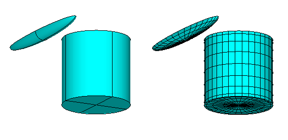
Input file: test13.cfg
! TEST13.CFG -- Cylinder + spheroid, ILOWHI=1
IPLTDAT=4
ILOWHI=1
IRR=0
ISOLVE=2
KSPLIN=3
IQUADO=3
IQUADI=4
NUMHDR=1
NOOUT=0 1 1 1 0 1 1 1 1
IALTFRC = 3 ! Alternative Form 3 FRC
IALTFRCN= 1 1
Input file: test13.pot
TEST13.POT -- Cylinder + spheroid, ILOWHI=1
-1.
1 1 IRAD, IDIFF
2 NPER (array PER follows)
1.5 2.0 PER
1 NBETA (array BETA follows)
0. BETA
2 NBODY
test13c.gdf
1.25 0.0 0.0 0.0 XBODY
1 1 1 1 1 1 IMODE(1-6)
test13s.gdf
-0.5 0.0 0.0 90.0 XBODY
1 1 1 1 1 1 IMODE(1-6)
Input file: test13c.gdf
TEST13C cylinder R=1 T=2 -- analytic geometry (npatch=2)
1. 9.80665 ULEN GRAV
1 1 ISX ISY
2 -1 NPATCH IGDEF
2 NLINES
1.0 2.0 RADIUS, DRAFT
1 UNIFORM MAPPING
Input file: test13c.spl
TEST13C cylinder R=1 T=2 -- analytic geometry (npatch=2)
8 8 NU NV (side)
8 4 NU NV (bottom)
Input file: test13s.gdf
TEST13S spheroid a=2, b=c=0.25 -- igdef=-4
1. 9.80665 ULEN GRAV
1 1 ISX ISY
1 -4 NPATCH IGDEF
1 NLINES
2.0 0.25 0.25 A, B, C
Input file: test13s.spl
TEST13S spheroid A=2 B=C=.25 -- analytic geometry (npatch=1)
8 4 NU NV
Input file: test13.frc
TEST13.FRC -- Cylinder + spheroid, ILOWHI=1
1 1 1 1 1 3 1 1 1
1.0
test05c.frc
test05s.frc
0
1
0. 0. 0.
Input file: test13c.csf
test13c.csf cylinder control surface
1 ILOWHICSF
1 1 ISX ISY
3 -1001 1. NPATCH ICDEF PSZCSF
2
1.2 2.2 1. RADIUS, DRAFT , Inner radius
0 uniform mapping
Input file: test13s.csf
ELLIPSOID CONTROL SURFACE defined by subroutine ELLIPSOID\_CS
1 ILOWHICSF
1 1 ISX ISY
2 -1003 1.0 NPATCH IGDEF PSZCSF
2 NLINES
2.2 0.3 0.3 A, B, C (semi-axes of outer control surface)
2.0 0.25 (semi-axes of body waterline)
TEST13A illustrates the use of trimmed waterlines, as specified by the last three lines of the file TEST13A.CFG. The cylinder is raised vertically by 1m, and rotated about the pitch axis by 15 degrees. The options IRR=3 and IRR=1 are used to remove irregular frequency effects, as described in Section 9.4. The interior free surface of the spheroid is defined by the GDF file and subroutine ELLIPSOID, with IRR=1 (See Sections 6.8 and 9.1). The interior free surface of the trimmed cylinder is defined automatically by the program, based on the trimmed waterline, with IRR=3 (See Section 9.4). (Since the cylinder is trimmed the waterplane is elliptical, and the IRR=1 extension of CIRCCYL in GEOMXACT is not valid.) Note that NPATCH=2 is assigned in test13as.gdf, to provide for the interior free surface, and test13as.spl includes the spline parameters NU,NV for this extra patch. Conversely for the cylinder the input files test13ac.gdf and test13ac.spl do not include the extra patch since this is added by the program using IRR=3.
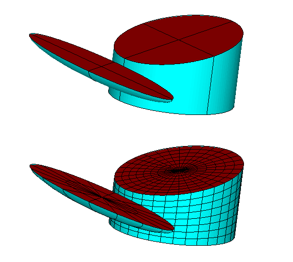
Input file: test13a.cfg
! TEST13A.CFG -- Cylinder + spheroid with trim
IPLTDAT=4
ILOWHI=1
IRR(1)=3
IRR(2)=1
ILOG=1
ISOLVE=1
KSPLIN=3
IQUADO=3
IQUADI=4
NUMHDR=1
NOOUT=0 1 1 1 0 1 1 1 1
IALTFRC = 3 ! Alternative Form 3 FRC
IALTFRCN= 1 1
ITRIMWL=1 trim waterline
XTRIM(1)= 1.0 15. 0.
XTRIM(2)= 0.0 0. 0.
Input file: test13a.pot
test13a.POT -- Trimmed Cylinder + spheroid, IRR=3
-1.
1 1 IRAD, IDIFF
2 NPER (array PER follows)
1.00 2.00
1 NBETA (array BETA follows)
0.
2 NBODY
test13ac.gdf
1.25 0.0 0.0 0.0 XBODY
1 1 1 1 1 1 IMODE(1-6)
test13as.gdf
-0.5 0.0 0.0 90.0 XBODY
1 1 1 1 1 1 IMODE(1-6)
Input file: test13ac.gdf
test13ac.gdf -- Cylinder, trimmed, no interior free surface
1. 9.80665 ULEN GRAV
1 1 ISX ISY
2 -1 NPATCH IGDEF
2 NLINES
1.0 2.0 RADIUS, DRAFT
0 UNIFORM MAPPING
Input file: test13as.gdf
test13as.gdf -- untrimmed spheroid with interior free surface
1. 9.80665 ULEN GRAV
1 1 ISX ISY
2 -4 NPATCH IGDEF
1 NLINES
2.0 0.25 0.25 A, B, C
Input file: test13ac.spl
TEST13C cylinder R=1 T=2 -- analytic geometry (npatch=2)
8 8 NU NV (side)
8 4 NU NV (bottom)
Input file: test13as.spl
test13as.spl -- untrimmed spheroid with interior free surface
4 2 body patch NU NV
4 2 interior fs NU NV
Input file: test13a.frc
TEST13a.FRC -- Cylinder + spheroid, trimmed waterlines
1 1 1 1 0 3 0 1 1
1.0
test05c.frc
test05s.frc
0
1
0. 1. 0.
A.14 ISSC TLP – TEST14
The subroutine TLP (IGDEF=-9) is used to generate the ISSC TLP with the dimensions specified in TEST14.GDF. The same structure is analysed in the low-order test runs TEST06 and TEST06a. As explained in Appendix A.6 a warning message is displayed for Options 8 and 9 since IDIFF=0.
For TEST14a, TEST14a.CFG TEST14a.POT and TEST14a.FRC are used to output data to be used as input to F2T. TEST14.GDF and TEST14.SPL are used without change. TEST14a.POT has zero and infinite frequencies and 99 uniformly spaced additional frequencies. IPERIN=2 is specified in the cfg file. In FRC, IOPTN(4) is set to output the RAOs in all six modes.
Since there are a large number of wave frequencies in TEST14a, it is a good example of the benefit of multiple processors (See Section 14.6). The runtimes in this case using NCPU=1,2,4,8 are almost inversely proportional to NCPU.
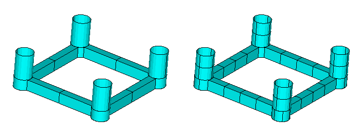
Input file: test14.cfg
! TEST14.CFG -- ISSC TLP (ILOWHI=1)
ipltdat=5
ILOWHI=1
IRR=0
ISOLVE=1
IQUADI=4
IQUADO=3
KSPLIN=3
NUMHDR=1
IALTFRC=2
Input file: test14.pot
TEST14 -- ISSC TLP (ILOWHI=1)
450
0 0 IRAD, IDIFF
3 NPER (array PER follows)
5. 10. 15.
1 NBETA (array BETA follows)
0.
1 NBODY
test14.gdf
0. 0. 0. 0. XBODY
1 0 1 0 1 0 IMODE(1-6)
Input file: test14.gdf
TEST14 -- ISSC TLP (ILOWHI=1)
43.125 9.80665 ULEN GRAV
1 1 ISX ISY
12 -9 NPATCH, IGDEF
2 NLINES
8.435 35. 43.125 RADIUS DRAFT HSPACE
7.5 10.5 WIDTH HEIGHT
Input file: test14.spl
TEST14 -- ISSC TLP (ILOWHI=1)
1 2 NU NV patch 1
1 2 NU NV patch 2
1 2 NU NV patch 3
1 2 NU NV patch 4
1 2 NU NV patch 5
1 2 NU NV patch 6
1 2 NU NV patch 7
1 2 NU NV patch 8
4 1 NU NV patch 9
4 2 NU NV patch 10
4 1 NU NV patch 11
1 1 NU NV patch 12
Input file: test14.frc
TEST14 -- ISSC TLP (ILOWHI=1, IALTFRC=2)
1 1 1 -2 0 0 0 1 1 IOPTN (IOPTN(4)<0 signifies fixed modes)
6 NDFR
1 1 0 0 0 1 IMODE
1. RHO
0. 0. 3.0 XCG
1 IMASS
53066.4 0. 0. 0. 159199.2 0.
0. 53066.4 0. -159199.2 0. 0.
0. 0. 53066.4 0. 0. 0.
0. -159199.2 0. 8.0201552E7 0. 0.
159199.2 0. 0. 0. 8.0201552E7 0.
0. 0. 0. 0. 0. 9.54906731E7
0 IDAMP
0 ISTIFF
0 NBETAH
0 NFIELD
Input file: test14a.cfg
ILOWHI=1
IRR=0
ISOLVE=1
IQUADI=4
IQUADO=3
KSPLIN=3
NUMHDR=1
IALTFRC=2
IPERIN=2
IPEROUT=2
Input file: test14a.pot
TEST14A -- ISSC TLP (ILOWHI=1)
450
0 0 IRAD, IDIFF
-101 NPER (array PER follows)
-0.05 0.05
1 NBETA (array BETA follows)
0.
1 NBODY
test14.gdf
0. 0. 0. 0. XBODY
1 0 1 0 1 0 IMODE(1-6)
Input file: test14a.frc
TEST14A -- ISSC TLP (ILOWHI=1, IALTFRC=2)
1 1 1 1 0 0 0 0 0 IOPTN
1. RHO
0. 0. 3.0 XCG
1 IMASS
53066.4 0. 0. 0. 159199.2 0.
0. 53066.4 0. -159199.2 0. 0.
0. 0. 53066.4 0. 0. 0.
0. -159199.2 0. 8.0201552E7 0. 0.
159199.2 0. 0. 0. 8.0201552E7 0.
0. 0. 0. 0. 0. 9.54906731E7
0 IDAMP
0 ISTIFF
0 NBETAH
0 NFIELD
A.15 SEMI-SUB – TEST15
The subroutine SEMISUB (IGDEF=-10) is used to generate a Semi-submersible with the dimensions specified in TEST15.GDF. There are five columns on each pontoon, as shown in the figures below. For this structure a total of 10 patches are required. If NPATCH=11, extensions of the pontoons can be included as explained in the subroutine comments.
Option 7 is used to evaluate the drift force and moment from the method described in Chapter 11. The control surface is defined by the program, using the automatic method described in Section 11.4, with the input parameters specified in the CSF file. The outer control surface is a rectangular box, and three inner partitions are defined to separate the columns, as discussed in Example 4 of Section 11.4.

Input file: test15.cfg
! TEST15.CFG -- Semi-sub with five columns on each pontoon
ipltdat=1
ISOLVE=1
NUMHDR=1
KSPLIN=3
IQUADI=4
IQUADO=3
ILOWHI=1
Input file: test15.pot
TEST15 Semi-sub with five columns on each pontoon
-1.
0 0 IRAD, IDIFF
1 NPER (array PER follows)
18.0
1 NBETA (array BETA follows)
180.
1 NBODY
test15.gdf
0. 0. 0. 0. XBODY
0 0 1 0 1 0 IMODE(1-6)
Input file: test15.gdf
TEST15 Semi-sub, NCOL=5, IGDEF=-10
1. 9.80665 ULEN GRAV
1 1 ISX ISY
10 -10 NPATCH IGDEF
2 NLINES
260. 20. 40. -30. -20. XL, Y1, Y2, Z1, Z2
60. 8. 5 DCOL, RCOL, NCOL
Input file: test15.spl
TEST15 Semi-sub, NCOL=5, IGDEF=-10
9 2 NU NV (patch 10+32 - pontoon bottom)
32 1 NU NV (patch 9+32 - pontoon side)
2 2 NU NV (patch 1+32 - column 3)
2 1 NU NV (patch 2+32 - annulus 3)
5 2 NU NV (patch 3+32 - between annulus 3&4)
4 2 NU NV (patch 4+32 - column 4)
4 1 NU NV (patch 5+32 - annulus 4)
5 2 NU NV (patch 6+32 - between annulus 4&5)
4 2 NU NV (patch 7+32 - column 5)
4 1 NU NV (patch 8+32 - annulus 5)
Input file: test15.frc
TEST15 Semi-sub with five columns on each pontoon
1 1 1 1 0 0 1 1 1
0.0000
20.0 0.0 0.0
0. 60.0 0.0
0 0. 60.0
0
0
Input file: test15.csf
test15.csf semi sub, outer box 150*60*40
1 ILOWHICSF
1 1 ISX ISY
0 0 10. NPATCH ICDEF PSZCSF (1st two indicate this is automatic)
0.0 40.0 RADIUS, DRAFT of outer box
4 NPART
3 nv0
150.0 0.0
150.0 60.0
0.0 60.0 end of partition line 0 (outer boundary of control surface)
3 nv1
0.0 0.0
30.0 0.0
30.0 50.0
4 nv2
30.0 50.0
30.0 0.0
90.0 0.0
90.0 50.0
3 nv3
90.0 50.0
90.0 0.0
150.0 0.0 end of partition line column 3
A.16 BARGE WITH BENDING MODES – TEST16
The test runs TEST16 and TEST16a analyze the structural response of a rectangular barge with total length 80m, beam 10m, and draft 5m. Eight free-free beam modes are included to analyze the elastic deformation of the barge. These mode shapes are defined in the NEWMODES subroutine FREEBEAM_X and the length is input to this subroutine using the file test16_Length.dat, as described in Section 9.3. The response amplitude of each mode is included in the RAO’s.
In TEST16 the subroutine BARGE (IGDEF=-5) is used. The half-length, half-beam and draft are specified in TEST16.GDF. In TEST16a the option IGDEF=0 is used, with the vertices of the patches specified in TEST16a.GDF in the same format as for low-order panels.
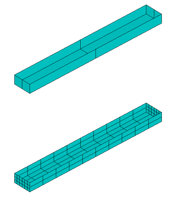
Input file: test16.cfg
! TEST16.CFG elastic barge with 8 beam modes
ipltdat=5
ilowgdf=5
ILOWHI=1
IALTFRC=2
ISOLVE=1
IQUADI=5
IQUADO=4
MONITR=0
NUMHDR=1
IGENMDS=16
NEWMDS=8
Input file: test16.pot
TEST16 elastic barge with 8 beam modes
-1.
0 0 IRAD, IDIFF
2 NPER (array PER follows)
7. 8.
1 NBETA (array BETA follows)
180.
1 NBODY
test16.gdf
0. 0. 0. 0. XBODY
1 0 1 0 1 0 IMODE(1-6)
Input file: test16.gdf
TEST16 elastic barge
1. 9.80665 ULEN GRAV
1 1 ISX ISY
3 -5 NPATCH IGDEF
1 NLINES
40.0 5.0 5.0 half-length, half-beam, draft
Input file: test16.spl
TEST16 elastic barge
3 3 NU NV (end)
4 4 KU KV
5 2 (side)
4 4
5 2 (bottom)
4 4
IQUO IQVO are not specified IQUADO=3 in config.wam
IQUI IQVI are not specified IQUADI=4 in config.wam
Input file: test16.frc
TEST16 elastic barge with 8 beam modes
1 1 1 1 0 0 0 0 0
1000.
0. 0. 0.
1
4.00000E+06 0. 0. 0. 0. 0. 0. 0. 0. 0. 0. 0. 0. 0.
0. 0. 0. 0. 0. 0. 0. 0. 0. 0. 0. 0. 0. 0.
0. 0. 4.E+06 0. 0. 0. 0. 0. 0. 0. 0. 0. 0. 0.
0. 0. 0. 0. 0. 0. 0. 0. 0. 0. 0. 0. 0. 0.
0. 0. 0. 0. 2.13333E+09 0. 0. 0. 0. 0. 0. 0. 0. 0.
0. 0. 0. 0. 0. 0. 0. 0. 0. 0. 0. 0. 0. 0.
0. 0. 0. 0. 0. 0. 1.E+06 0. 0. 0. 0. 0. 0. 0.
0. 0. 0. 0. 0. 0. 0. 1.E+06 0. 0. 0. 0. 0. 0.
0. 0. 0. 0. 0. 0. 0. 0. 1.E+06 0. 0. 0. 0. 0.
0. 0. 0. 0. 0. 0. 0. 0. 0. 1.E+06 0. 0. 0. 0.
0. 0. 0. 0. 0. 0. 0. 0. 0. 0. 1.E+06 0. 0. 0.
0. 0. 0. 0. 0. 0. 0. 0. 0. 0. 0. 1.E+06 0. 0.
0. 0. 0. 0. 0. 0. 0. 0. 0. 0. 0. 0. 1.E+06 0.
0. 0. 0. 0. 0. 0. 0. 0. 0. 0. 0. 0. 0. 1.E+06
0
1
0. 0. 0. 0. 0. 0. 0. 0. 0. 0. 0. 0. 0. 0.
0. 0. 0. 0. 0. 0. 0. 0. 0. 0. 0. 0. 0. 0.
0. 0. 0. 0. 0. 0. 0. 0. 0. 0. 0. 0. 0. 0.
0. 0. 0. 0. 0. 0. 0. 0. 0. 0. 0. 0. 0. 0.
0. 0. 0. 0. 0. 0. 0. 0. 0. 0. 0. 0. 0. 0.
0. 0. 0. 0. 0. 0. 0. 0. 0. 0. 0. 0. 0. 0.
0. 0. 0. 0. 0. 0. 6.25705E+06 0. 0. 0. 0. 0. 0. 0.
0. 0. 0. 0. 0. 0. 0. 4.75441E+07 0. 0. 0. 0. 0. 0.
0. 0. 0. 0. 0. 0. 0. 0. 1.82720E+08 0. 0. 0. 0. 0.
0. 0. 0. 0. 0. 0. 0. 0. 0. 4.99297E+08 0. 0. 0. 0.
0. 0. 0. 0. 0. 0. 0. 0. 0. 0. 1.11419E+09 0. 0. 0.
0. 0. 0. 0. 0. 0. 0. 0. 0. 0. 0. 2.17352E+09 0. 0.
0. 0. 0. 0. 0. 0. 0. 0. 0. 0. 0. 0. 3.85260E+09 0.
0. 0. 0. 0. 0. 0. 0. 0. 0. 0. 0. 0. 0. 6.35602E+09
0
0
Input file: test16a.pot
TEST16a elastic barge with 8 beam modes - igdef=0
-1.
0 0 IRAD, IDIFF
2 NPER (array PER follows)
7. 8.
1 NBETA (array BETA follows)
180.
1 NBODY
test16a.gdf
0. 0. 0. 0. XBODY
1 0 1 0 1 0 IMODE(1-6)
First 10 lines of input file: test16a.gdf
TEST16a elastic barge with 8 beam modes - igdef=0 (3 flat panels)
1.0000 9.80665
1 1
3 0 NPATCH, IGDEF
40.0000 0.000000 -5.00000
40.0000 5.00000 -5.00000
40.0000 5.00000 0.000000
40.0000 0.000000 0.000000 (end)
40.0000 5.00000 -5.00000
0.000000 5.00000 -5.00000
Input file: test16a.spl
TEST16A elastic barge with igdef=0 (patches defined by flat panels)
3 3 NU NV end
4 4 KU KV
5 2 side
4 4
5 2 bottom
4 4
Input file: test16a.frc
TEST16a elastic barge with 8 beam modes (igdef=0)
1 1 1 1 0 0 0 0 0
1000.
0. 0. 0.
1
4.00000E+06 0. 0. 0. 0. 0. 0. 0. 0. 0. 0. 0. 0. 0.
0. 0. 0. 0. 0. 0. 0. 0. 0. 0. 0. 0. 0. 0.
0. 0. 4.E+06 0. 0. 0. 0. 0. 0. 0. 0. 0. 0. 0.
0. 0. 0. 0. 0. 0. 0. 0. 0. 0. 0. 0. 0. 0.
0. 0. 0. 0. 2.13333E+09 0. 0. 0. 0. 0. 0. 0. 0. 0.
0. 0. 0. 0. 0. 0. 0. 0. 0. 0. 0. 0. 0. 0.
0. 0. 0. 0. 0. 0. 1.E+06 0. 0. 0. 0. 0. 0. 0.
0. 0. 0. 0. 0. 0. 0. 1.E+06 0. 0. 0. 0. 0. 0.
0. 0. 0. 0. 0. 0. 0. 0. 1.E+06 0. 0. 0. 0. 0.
0. 0. 0. 0. 0. 0. 0. 0. 0. 1.E+06 0. 0. 0. 0.
0. 0. 0. 0. 0. 0. 0. 0. 0. 0. 1.E+06 0. 0. 0.
0. 0. 0. 0. 0. 0. 0. 0. 0. 0. 0. 1.E+06 0. 0.
0. 0. 0. 0. 0. 0. 0. 0. 0. 0. 0. 0. 1.E+06 0.
0. 0. 0. 0. 0. 0. 0. 0. 0. 0. 0. 0. 0. 1.E+06
0
1
0. 0. 0. 0. 0. 0. 0. 0. 0. 0. 0. 0. 0. 0.
0. 0. 0. 0. 0. 0. 0. 0. 0. 0. 0. 0. 0. 0.
0. 0. 0. 0. 0. 0. 0. 0. 0. 0. 0. 0. 0. 0.
0. 0. 0. 0. 0. 0. 0. 0. 0. 0. 0. 0. 0. 0.
0. 0. 0. 0. 0. 0. 0. 0. 0. 0. 0. 0. 0. 0.
0. 0. 0. 0. 0. 0. 0. 0. 0. 0. 0. 0. 0. 0.
0. 0. 0. 0. 0. 0. 6.25705E+06 0. 0. 0. 0. 0. 0. 0.
0. 0. 0. 0. 0. 0. 0. 4.75441E+07 0. 0. 0. 0. 0. 0.
0. 0. 0. 0. 0. 0. 0. 0. 1.82720E+08 0. 0. 0. 0. 0.
0. 0. 0. 0. 0. 0. 0. 0. 0. 4.99297E+08 0. 0. 0. 0.
0. 0. 0. 0. 0. 0. 0. 0. 0. 0. 1.11419E+09 0. 0. 0.
0. 0. 0. 0. 0. 0. 0. 0. 0. 0. 0. 2.17352E+09 0. 0.
0. 0. 0. 0. 0. 0. 0. 0. 0. 0. 0. 0. 3.85260E+09 0.
0. 0. 0. 0. 0. 0. 0. 0. 0. 0. 0. 0. 0. 6.35602E+09
0
0
A.17 CYLINDER WITH MOONPOOL – TEST17
This test run illustrates several alternative methods for analyzing bodies with moonpools. The geometry used is the circular cylinder with a fluid column within a concentric inner cylinder, as shown in the figure. The inner column of fluid, referred to as a ‘moonpool’, is open at the bottom of the cylinder to the external fluid domain. The top of the moonpool is a free surface with atmospheric pressure. One of the practical aspects of this problem is the existence of highly tuned resonant frequencies of the motion at the moonpool free surface. If the draft is comparable or large compared to the horizontal dimensions of the moonpool, the principal resonance is a ‘pumping mode’ which occurs when Kd, the product of the wavenumber K and draft d is slightly less than one. Additional resonances occur in ‘sloshing modes’ at higher frequencies, corresponding approximately to standing waves inside the moonpool.
The same cylinder used in TEST02 is used here with the higher-order method. The outer radius is 0.5m, inner radius 0.25m and draft 1m. The geometry is represented analytically by the subroutine CYLMP (IGDEF=-7). Three patches are used to represent the outer side r=RADIUS, the annular bottom z =-DRAFT, and the inner side r=RADMP. The free surface inside the moonpool is part of the physical free surface, and the appropriate free-surface boundary condition is satisfied by the Green function as described in Chapter 15. The sides of one quadrant are omitted in the figures below, to show the bottom and moonpool more clearly.
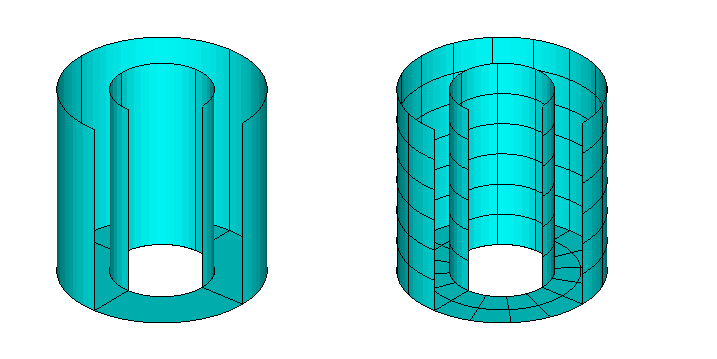
To clarify the behavior near resonance, the wavenumber K is input in the POT file with the corresponding options IPERIN=3 and IPEROUT=3 specified in the TEST17.cfg file. 61 values of K are input in the range 0.1 ≤ K ≤ 1.5 to describe the behavior near resonance. The input file test17.pot uses the optional parameter NPERGROUP to define thes wavenumbers, as described in Section 4.2. The computed hydrodynamic parameters include the force coefficients, RAO’s, and the elevation of the free surface at the center of the moonpool.
When the structure is fixed in heave the resonant pumping mode in the moonpool occurs at Kd = 0.85. The outputs related to the vertical force component display singular features near this point. This includes large amplitudes of the heave damping and exciting force, and negative added mass. The heave RAO has two adjacent resonant peaks as shown in Figure A.4, due to coupling between the heave mode and the moonpool pumping mode.
These very large responses are non-physical, and their existence in the computations can be attributed primarily to the neglect of viscous damping associated with flow separation at the outer and inner corners of the cylinder. This damping is only important when the vertical motions of the cylinder and/or moonpool are large.
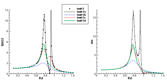
Input file: test17.cfg
! TEST17.CFG file, cylinder with moonpool
ipltdat=5
ilowgdf=5
ILOWHI=1
IALTFRC=1
ISOLVE=1
PANEL_SIZE = 0.2 (use default .spl parameters)
IPERIN=3 (input wavenumber)
IPEROUT=3 (output wavenumber)
NUMHDR=1
Input file: test17.pot
TEST17 cylinder with moonpool, NPATCH=3
-1.
0 0 IRAD, IDIFF
NPERGROUP=3
-11
0.10 0.05 (end of group 1, K = 0.10 to 0.60)
-40
0.61 0.01 (end of group 2, K = 0.61 to 1.00)
-10
1.05 0.05 (end of group 3, K = 1.05 to 1.50)
1 NBETA (array BETA follows)
180.
1 NBODY
test17.gdf
0. 0. 0. 0. XBODY
1 0 1 0 1 0 IMODE(1-6)
Input file: test17.gdf
TEST17 cylinder with moonpool
1. 9.80665 ULEN GRAV
1 1 ISX ISY
3 -7 NPATCH IGDEF
1 NLINES
0.5 1.0 0.25 radius, draft, moonpool radius
Input file: test17.frc
TEST17.FRC Cylinder with moonpool
1 1 1 1 0 1 0 0 0 IOPTN(1-9)
0.000000 VCG
0.500000 .0000000 .0000000
.0000000 0.500000 .0000000
.0000000 .0000000 0.500000 XPRDCT
0 NBETAH
1 NFIELD
0.0 0.0 0.0
In order to damp the moonpool response and heave motions separately, a different physical problem is considered in Tests 17a and 17b, where a ‘lid’ is placed on the free surface of the moonpool as shown in the figure below. This lid is considered to be an extension of the body surface, and represented by an additional patch. Thus NPATCH=4 is assigned in test17a.gdf (and also in Test 17b). The geomxact subroutine CYLMP assigns the patch number 4 to be a circular disc of radius RADMP in the plane Z=0. However allowance must be made for the motions of the actual free surface relative to the body. This is done by defining appropriate generalized modes, which are nonzero only on patch 4. The most important mode is a vertical translation, assigned here in the file NEWMODES.DLL with the index j = 7. In Test17b a pitch rotation of the lid (j = 8) is also included to provide a more general deflection of the free surface. A more complete expansion can be introduced, but at the wavenumbers considered here and for head-sea incidence angle these two modes of motion are sufficient. These two generalized modes, physically analogous to pitch and heave but defined relative to the body, are introduced via the subroutine MOONPOOL_FS in NEWMODES.
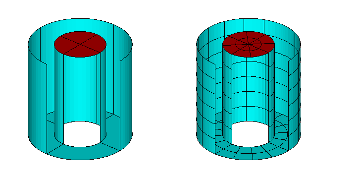
In test run TEST17a, the lid is assumed to be free with no external force or moment acting on it. The IALTFRC=2 option is employed, and the only external force matrix that is included in TEST17.FRC is the mass matrix of the body. This mass matrix is equivalent to the radii of gyration specified in TEST17.FRC. It can be confirmed by comparison of the outputs that the motions of the body (RAO) are virtually identical to TEST17, as shown in the Figure above, confirming that the representation of the moonpool free surface in this manner is legitimate. A comparison can also be made between the moonpool free surface elevation (numeric output file TEST17.6) and the response of the lid in mode 7 (RAO(7) in the numeric output file TEST17a.4), but in this comparison account must be made for the fact that RAO(7) is relative to the body motions, and thus it is necessary to compare the (complex) sum RAO(3)+RAO(7) in TEST17a with the moonpool free surface elevation in TEST17.
Input file: test17a.cfg
! TEST17A.CFG file, cylinder with moonpool, free lid
ipltdat=5
ilowgdf=5
ILOWHI=1
IALTFRC=2
ISOLVE=1
PANEL_SIZE = 0.2 (use default .spl parameters)
IPERIN=3 (input wavenumber)
IPEROUT=3 (output wavenumber)
ILOG=1
NUMHDR=1
IGENMDS=17
NEWMDS = 2
IPNLBPT=1 (evaluate field point at .bpi input)
TEST17 cylinder with moonpool + free lid, NPATCH=4
-1.
0 0 IRAD, IDIFF
NPERGROUP=3
-11
0.10 0.05 (end of group 1, K = 0.10 to 0.60)
-40
0.61 0.01 (end of group 2, K = 0.61 to 1.00)
-10
1.05 0.05 (end of group 3, K = 1.05 to 1.50)
1 NBETA (array BETA follows)
180.
1 NBODY
test17a.gdf
0. 0. 0. 0. XBODY
1 0 1 0 1 0 IMODE(1-6)
Input file: test17a.gdf
TEST17a cylinder with moonpool -- undamped patch on free surface
1. 9.80665 ULEN GRAV
1 1 ISX ISY
4 -7 NPATCH IGDEF
1 NLINES
0.5 1.0 0.25 radius, draft, moonpool radius
Input file: test17a.frc
TEST17a moonpool with generalized modes for free surface - no damping
1 1 1 1 1 0 0 0 0
1.
0. 0. 0.
1 imass (mass matrix of body)
0.589 0.0 0.0 0.0 0.0 0.0 0.0 0.0
0.0 0.589 0.0 0.0 0.0 0.0 0.0 0.0
0.0 0.0 0.589 0.0 0.0 0.0 0.0 0.0
0.0 0.0 0.0 0.147 0.0 0.0 0.0 0.0
0.0 0.0 0.0 0.0 0.147 0.0 0.0 0.0
0.0 0.0 0.0 0.0 0.0 0.147 0.0 0.0
0.0 0.0 0.0 0.0 0.0 0.0 0.0 0.0
0.0 0.0 0.0 0.0 0.0 0.0 0.0 0.0
0 idamp
0 istif
0
0
Input file: test17a.bpi
test17d.bpi file
1
0.0 0.0 0.0
In TEST17b, empirical damping is introduced via the external damping matrix in TEST17b.FRC. Since this is the only difference between TEST17a and TEST17b, it is not necessary to re-run POTEN and the same TEST17a.P2F file is used for TEST17b. Thus TEST17a.pot is specified in FNAMES.17b, and IPOTEN=0 in the TEST17b.cfg file. The only nonzero elements of the external damping matrix are for heave (j = 3) and the lid vertical motion (j = 7). With these empirical damping coefficients added, more appropriate RAO’s are obtained as shown in Figure A.4. This general approach can be refined based on experimental data. Experience with similar problems suggests that relatively crude estimates based on the observed response at resonance are sufficient to correct the response over a broad range of wave periods.
Input file: test17b.cfg
! TEST17B.CFG file, cylinder with moonpool, damped lid
ILOWHI=1
IPOTEN=0
IALTFRC=2
ISOLVE=1
PANEL_SIZE = 0.2 (use default .spl parameters)
IPERIN=3 (input wavenumber)
IPEROUT=3 (output wavenumber)
ILOG=1
NUMHDR=1
IGENMDS=17
NEWMDS = 2
Input file: test17b.frc
TEST17b cylinder+moonpool, generalized modes, damping b33=.4, b77=.1
1 1 1 1 0 0 0 0 0
1.
0. 0. 0.
1 imass (mass matrix of body)
0.589 0.0 0.0 0.0 0.0 0.0 0.0 0.0
0.0 0.589 0.0 0.0 0.0 0.0 0.0 0.0
0.0 0.0 0.589 0.0 0.0 0.0 0.0 0.0
0.0 0.0 0.0 0.147 0.0 0.0 0.0 0.0
0.0 0.0 0.0 0.0 0.147 0.0 0.0 0.0
0.0 0.0 0.0 0.0 0.0 0.147 0.0 0.0
0.0 0.0 0.0 0.0 0.0 0.0 0.0 0.0
0.0 0.0 0.0 0.0 0.0 0.0 0.0 0.0
1 idamp
0.0 0.0 0.0 0.0 0.0 0.0 0.0 0.0
0.0 0.0 0.0 0.0 0.0 0.0 0.0 0.0
0.0 0.0 0.4 0.0 0.0 0.0 0.0 0.0
0.0 0.0 0.0 0.0 0.0 0.0 0.0 0.0
0.0 0.0 0.0 0.0 0.0 0.0 0.0 0.0
0.0 0.0 0.0 0.0 0.0 0.0 0.0 0.0
0.0 0.0 0.0 0.0 0.0 0.0 0.1 0.0
0.0 0.0 0.0 0.0 0.0 0.0 0.0 0.0
0 istif
0
0
In Tests 17c and 17d the external damping option described in Section 12.8 is used. Two dipole damper surfaces are included as skirts at the lower edges of the cylinder, as shown in the figure below, with dimensions indicated in the file test17c.gdf. The geomxact subroutine CYLDIPMP is used to define the body and skirts. In Test17c the dipole dampers are free, with IDAMPER=1 specified in the test17c.cfg file. In Test17d the dipole dampers are fixed, with IDAMPER=2 specified in the test17d.cfg file. Since the other inputs are the same, test17c.gdf is used for both runs. The damping parameters EDAMPER=0.1 and 0.4 are specified in test17c.dmp. The Haskind exciting force is not valid in these cases, and thus ioptn(4)=2 is assigned in the frc files to evaluate the RAO’s from the diffraction exciting force.
The heave RAO and moonpool elevation are shown in Figure A.4. The values of EDAMPER can be varied to modify these results.
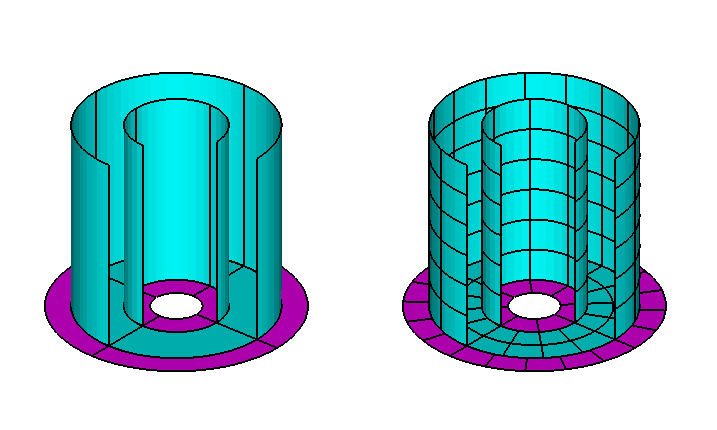
Input file: test17c.cfg
! TEST17c.CFG cylinder with moonpool + 2 dipole damper skirts
ipltdat=5
ILOWHI=1
ISOLVE=1
PANEL_SIZE = 0.2 (use default .spl parameters)
IPERIN=3 (input wavenumber)
IPEROUT=3 (output wavenumber)
ILOG=1
NUMHDR=1
idamper=1
npdipole=4 5
Input file: test17c.pot
TEST17c cylinder with moonpool + 2 dipole damper skirts
-1.
0 0 IRAD, IDIFF
NPERGROUP=3
-11
0.10 0.05 (end of group 1, K = 0.10 to 0.60)
-40
0.61 0.01 (end of group 2, K = 0.61 to 1.00)
-10
1.05 0.05 (end of group 3, K = 1.05 to 1.50)
1 NBETA (array BETA follows)
180.
1 NBODY
test17c.gdf
0. 0. 0. 0. XBODY
1 0 1 0 1 0 IMODE(1-6)
Input file: test17c.gdf
TEST17c cylinder with moonpool + dipole damper skirts
1. 9.80665 ULEN GRAV
1 1 ISX ISY
5 -34 NPATCH IGDEF
4 nlines
1 2 NMP,NDIP
0.5 1.0 0.25 radius, draft, moonpool radius
0.625 0.5 1.0 outer skirt outer/inner radii, depth
0.25 0.125 1.0 inner skirt outer/inner radii, depth
Input file: test17c.dmp
test17c.dmp file, edamper=0.1, 0.4
2 ndampers
4 4 npdamper (outer skirt)
0.1 edamper
5 5 npdamper (inner skirt)
0.4 edamper
Input file: test17c.frc
TEST17c moonpool with 2 dipole damper skirts
1 0 1 2 0 1 0 0 0 IOPTN(1-9)
0.000000 VCG
0.500000 .0000000 .0000000
.0000000 0.500000 .0000000
.0000000 .0000000 0.500000 XPRDCT
0 NBETAH
1 NFIELD
0.0 0.0 0.0
Input file: test17d.cfg
! TEST17d.CFG cylinder with moonpool + fixed damper skirts
ipltdat=5
ILOWHI=1
ISOLVE=1
PANEL_SIZE = 0.2 (use default .spl parameters)
IPERIN=3 (input wavenumber)
IPEROUT=3 (output wavenumber)
ILOG=1
NUMHDR=1
npdipole=4 5 dipole patches
idamper=2 fixed dampers
Input file: test17d.pot
TEST17d cylinder with moonpool + fixed damper skirts
-1.
0 0 IRAD, IDIFF
-8
0.5 0.1
1 NBETA (array BETA follows)
180.
1 NBODY
test17c.gdf (same gdf and dmp as test17c)
0. 0. 0. 0. XBODY
1 0 1 0 1 0 IMODE(1-6)
Input file: test17d.frc
TEST17d cylinder + moonpool with fixed damper skirts
1 0 1 2 0 1 0 0 0 IOPTN(1-9)
0.000000 VCG
0.500000 .0000000 .0000000
.0000000 0.500000 .0000000
.0000000 .0000000 0.500000 XPRDCT
0 NBETAH
1 NFIELD
0.0 0.0 0.0 XFIELD
A.18 ELASTIC COLUMN – TEST18
The same inputs are used as in the low-order test run TEST08, except for the GDF file. The circular column is represented by the subroutine CIRCCYL (IGDEF=-1). Since the cylinder is bottom-mounted, NPATCH=1 and the patch on the bottom of the cylinder is omitted. The draft is set equal to the fluid depth. IGENMDS=18 is assigned in CFG file, and in NEWMODES this results in a call to subroutine JACOBI for the four shifted Jacobi polynomials, as described in Section 9.3.
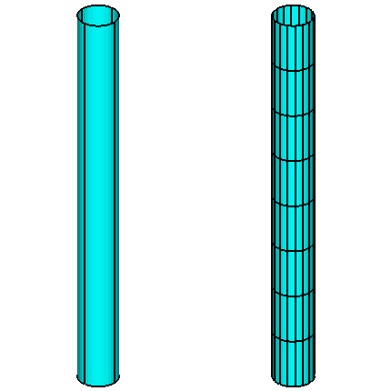
Input file: test18.cfg
! TEST18.CFG -- bending of vertical column with 4 generalized modes
ipltdat=5
ilowgdf=5
ISOLVE=1
NUMHDR=1
NUMNAM=0
NEWMDS=4
ILOWHI=1
IALTFRC=2
KSPLIN=3
IQUADO=3
IQUADI=4
IGENMDS=18
Input file: test18.pot
TEST18.POT -- bending of vertical column at resonance, 200m depth
200.0 HBOT
0 0 IRAD,IDIFF
1
6.5
1
0.0
1 NBODY
test18.gdf
0.0 0.0 0.0 0.0
0 0 0 0 0 0
Input file: test18.gdf
TEST18.GDF vertical cylinder, bottom mounted
1.0000 9.80665 ulen, grav
1 1 isx,isy
1 -1 npatch, igdef
2 NLINES
10.0000 200.000 radius, draft
0 uniform mapping
Input file: test18.spl
TEST18.spl - bottom-mounted cylinder R=10 T=200 -- (npatch=1)
4 8 NU NV (Patch 1, side u azimuthal v vertical)
Input file: test18.frc
TEST18.FRC file, vertical column with 4 bending modes
1 1 1 1 0 0 0 0 0
1.0
.0000000 .0000000 1.000000
1
0. 0. 0. 0. 0. 0. 0. 0. 0. 0.
0. 0. 0. 0. 0. 0. 0. 0. 0. 0.
0. 0. 0. 0. 0. 0. 0. 0. 0. 0.
0. 0. 0. 0. 0. 0. 0. 0. 0. 0.
0. 0. 0. 0. 0. 0. 0. 0. 0. 0.
0. 0. 0. 0. 0. 0. 0. 0. 0. 0.
0. 0. 0. 0. 0. 0. 69115. 62832. 62832. 62832.
0. 0. 0. 0. 0. 0. 62832. 67320. 62832. 62832.
0. 0. 0. 0. 0. 0. 62832. 62832. 66323. 62832.
0. 0. 0. 0. 0. 0. 62832. 62832. 62832. 65688.
0
1
0. 0. 0. 0. 0. 0. 0. 0. 0. 0.
0. 0. 0. 0. 0. 0. 0. 0. 0. 0.
0. 0. 0. 0. 0. 0. 0. 0. 0. 0.
0. 0. 0. 0. 0. 0. 0. 0. 0. 0.
0. 0. 0. 0. 0. 0. 0. 0. 0. 0.
0. 0. 0. 0. 0. 0. 0. 0. 0. 0.
0. 0. 0. 0. 0. 0. 103044. 412177. 824354. 1339575.
0. 0. 0. 0. 0. 0. 412177. 4430902. 9789203. 16487078.
0. 0. 0. 0. 0. 0. 824354. 9789203. 37899671. 64382041.
0. 0. 0. 0. 0. 0. 1339575. 16487078. 64382041. 162406554.
0
0
A.19 CATAMARAN BARGE – TEST19
The geometrical configuration is the same as the barge near a wall (TEST04). Since only head seas are considered, the hydrodynamic outputs correspond to TEST04 except for the different definition of the incident wave amplitude which applies for a body near a wall. In TEST19 IGDEF=0 is used, with four patches specified in the GDF file corresponding to one quadrant of the catamaran configuration. Since there are two hulls in this case, the forces acting on both hulls are two times the corresponding forces in TEST04, but since the incident wave amplitude in TEST04 is increased by a factor of two, the exciting force coefficients and RAO’s are the same in both test runs, except for small differences in accuracy. Note that in TEST19 two planes of symmetry can be utilized, unlike TEST04 where reflection about the plane x = 0 is required by the program. The comparisons of cross-coupling coefficients and Haskind/Diffraction exciting forces implies that the results of TEST19 are more accurate, with less computational cost.
Generalized modes can be used to extend the analysis of this configuration to include two independent bodies. In this case each of the rigid-body modes of the catamaran must be supplemented by a corresponding generalized mode which has the same normal velocity on one barge, and the opposite phase on the other. The separate modes of each independent body are then evaluated by combining the corresponding symmetric and antisymmetric modes for the catamaran. It is simpler to use the option NBODY=2 for this purpose. The subroutine BARGE (IGDEF=-5) is not suitable here, since this only represents one quadrant of one barge. On the other hand, BARGE can be used in the alternative NBODY=2 approach.
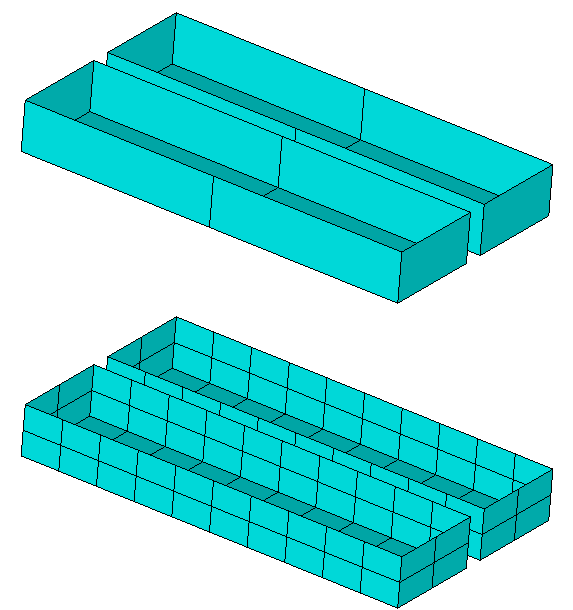
Input file: test19.cfg
! TEST19.CFG -- Catamaran barge
ipltdat=5
ILOWHI=1
IALTFRC=1
ISOLVE=1
IQUADI=5
IQUADO=4
MONITR=0
NUMHDR=1
Input file: test19.pot
TEST19.POT -- Catamaran barge, same geometry as TEST04
-1. HBOT
0 0 IRAD,IDIFF
3
6. 7. 8.
1
0.0
1 NBODY
test19.gdf
0. 0. 0. 0.
1 0 1 0 1 0
First 10 lines of input file: test19.gdf
TEST19 one quadrant of catamaran barge configuration
40. 9.80665 ULEN GRAV
1 1 ISX ISY
4 0 NPATCH IGDEF
40.0000 2.000000 -10.00000
40.0000 22.00000 -10.00000
40.0000 22.00000 0.000000
40.0000 2.000000 0.000000 (end)
40.0000 22.00000 -10.00000
0.000000 22.00000 -10.00000
Input file: test19.spl
TEST19 catamaran barge
2 2 NU NV (end)
4 4 KU KV
5 2 (outside)
4 4
5 2 (bottom)
4 4
5 2 (inside)
4 4
IQUO IQVO are not specified IQUADO=3 in config.wam
IQUI IQVI are not specified IQUADI=4 in config.wam
Input file: test19.frc
TEST19.FRC -- Catamaran barge, ILOWHI=1 (same as TEST04.FRC)
1 1 1 1 1 0 0 1 1
3.0
20.00000 0.000000 0.000000
0.000000 5.000000 0.000000
0.000000 0.000000 20.00000
0
0
A.20 MULTISURF BARGE – TEST20
This example illustrates the use of a MultiSurf geometry representation with IGDEF=2. The barge has a length of 100m, beam 20m, and draft 4.8m with one plane of symmetry (y = 0). The origin of the body coordinate system is at the intersection of the waterplane and midship section. The format of the GDF file is as explained in ?? and Appendix C. Four patches are used on one side of the body to represent the forebody, parallel middlebody, afterbody, and transom. Reference 24 includes results for a multiple-body configuration including two barge hulls identical to this model.
The body pressure is evaluated at the points specified in the input file test20.bpi, as explained in Section 4.11. The parameter IPNLBPT=1 in the .cfg file is used to specify this option with the input points specified in the body coordinate system.
Test 20a illustrates the use of the channel option described in Section 12.7. In this case the barge is on the centerline of a channel of width w =100m and depth 15m. Results for the heave and pitch RAO’s are shown in Figure A.5. (In order to reproduce all of the curves in this figure, the input files test20a.cfg and test20a.pot must be modified as noted below.)
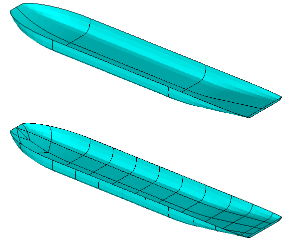
Input file: test20.cfg
! TEST20.CFG - MultiSurf barge
ipltdat=4
ILOWHI=1
IALTFRC=1
ISOLVE=1
NUMHDR=1
panel_size= 10.
IPNLBPT=1
Input file: test20.pot
single barge based on MultiSurf model (igdef=2)
-1.
1 1 IRAD, IDIFF
3 NPER (array PER follows)
6. 9. 12.
3 NBETA (array BETA follows)
180. 135. 90.
1 NBODY
test20.gdf
0.0 0.0 0.0 0.0 XBODY
1 1 1 1 1 1 IMODE(1-6)
Input file: test20.gdf
Test run for barge modelled with MultiSurf
1.000000 9.80665 ULEN, GRAV
0 1 ISX, ISY
0 2 NPATCH, IGDEF
3 NLINES
test20.ms2
wetted_surfs
0 0 0 FAST,DivMult, outward normals
Input file: test20.frc
test20.frc igdef=2
1 1 1 1 1 0 0 1 1 IOPTN(1-9)
0.0 VCG
10.00000 .0000000 .0000000
.0000000 25.00000 .0000000
.0000000 .0000000 25.00000 XPRDCT
0 NBETAH
0 NFIELD
First 10 lines of input file: test20.bpi
bpi input file for test20, body pressure points for MultiSurf barge
556
-44.7760 0.0000 -1.0074
-42.9240 0.0001 -1.8961
-45.0680 0.2891 -0.8477
-43.5610 0.6874 -1.6131
-45.3540 0.5549 -0.6847
-44.1780 1.2902 -1.3169
-40.8950 0.0006 -2.6665
-38.6880 0.0006 -3.3185
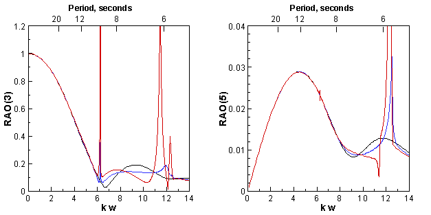
The input files for TEST20a are shown below. The wavenumber k is designated instead of the wave period, using the options IPERIN=4 and IPEROUT=4, to give a more physical understanding of the wall effects. A large number of closely-spaced wavenumbers are required to reproduce the curves shown in Figure A.5. These can be input by modifying test20a.pot to use the last group of lines of data in place of the two lines starting with NPER. The NPERGROUP option described in Section 4.2 is used in this case, to provide more closely-spaced wavenumbers where the curves in Figure A.5 change more rapidly.
The blue curve in Figure A.5 can be reproduced using the parameter CHANNEL_REFLECT in the cfg file, and the black curve for unbounded width can be reproduced by commenting out or removing the line with the parameter CHANNEL_WIDTH, or assigning this parameter with a value less than or equal to zero. It is not necessary to us a large number of closely-spaced wavenumbers in the latter case, as indicated by the ‘npergroup=5’ optional inputs following test20a.pot.
! TEST20a.CFG - MultiSurf barge in channel
ipltdat=4
ILOWHI=1
IALTFRC=1
ISOLVE=1
NUMHDR=1
panel_size= 10.
iperin=4
iperout=4
channel_width=100.0
! channel_reflect=0.5 (used for the blue line in Figure A.5)
Input file: test20a.pot
MultiSurf barge in channel
15.0
0 0 IRAD, IDIFF
-7 NPER
0.02 0.02 Coarse array of wavenumbers
1 NBETA (array BETA follows)
180.
1 NBODY
test20.gdf
0.0 0.0 0.0 0.0 XBODY
1 0 1 0 1 0 IMODE(1-6)
npergroup=5 ! group of wavenumbers used in Figure A.5
-60
.001 .001
-50
.0601 .0001
-35
.066 .001
-190
.1010 .0001
-20
.121 .001
Input file: test20a.frc
MultiSurf barge in channel
1 1 1 1 0 0 0 0 0 IOPTN(1-9)
0.0 VCG
10.00000 .0000000 .0000000
.0000000 25.00000 .0000000
.0000000 .0000000 25.00000 XPRDCT
0 NBETAH
0 NFIELD }
A.21 SPAR WITH THREE STRAKES – TEST21
The subroutine SPAR (IGDEF=-12) is used to generate the SPAR with three strakes with the dimensions specified in TEST21.GDF. Except for the geometry, the inputs correspond to the low-order test runs TEST09.
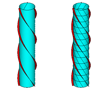
Input file: test21.cfg
! TEST21.CFG -- SPAR with three strakes
ipltdat=4
ilowgdf=4
ILOWHI=1
ISOLVE=1
KSPLIN=3
IQUADO=3
IQUADI=4
IPERIN=3 (input wavenumber)
IPEROUT=3 (output wavenumber)
MONITR=0
NUMHDR=1
NOOUT= 1 1 1 1 0 1 1 1 1
PANEL_SIZE=18
ILOG=1
NPDIPOLE = 2 4 6
Input file: test21.pot
TEST21.POT SPAR with three strakes igdef=-12 (TEST21.GDF)
-1.
1 1 IRAD, IDIFF
3 NPER (array PER follows)
0.1 0.5 1.
2 NBETA (array BETA follows)
0. 120.
1 NBODY
test21.gdf
0. 0. 0. 0. XBODY
1 1 1 1 1 1 IMODE(1-6)
Input file: test21.gdf
TEST21 SPAR2 with three strakes IGDEF=-12
18. 9.80665 ULEN GRAV
0 0 ISX ISY
7 -12 NPATCH IGDEF
5
18. 200. RADIUS, DRAFT
3.7 0. 1. 3 WIDTH, THICKNESS, TWIST, NSTRAKE
0 IRRFRQ
0 0. IMOONPOOL, RADIUSMP
0 IMPGEN
Input file: test21.frc
TEST21.FRC SPAR with three strakes igdef=-12
1 1 1 1 0 3 0 2 0
0.000000 VCG
100.000000 .0000000 .0000000
.0000000 100.000000 .0000000
.0000000 .0000000 10.000000 XPRDCT
0 NBETAH
2 NFIELD
23. 0. 0.
15. 15. -0.5 (end of file)
A.22 FPSO WITH TWO INTERNAL TANKS – TEST22
The subroutine FPSOINT (IGDEF=-21) is used to generate the FPSO with two internal tanks with the dimensions specified in TEST22.GDF. One plane of symmetry is specified, about y = 0. The tanks are rectangular, and the vertices of each patch are specified in TEST22.GDF. Both tanks have the same length (2m), breadth (4.2m), and depth (1.1m). The aft side of tank 1 and the forward side of tank 2 are in the same plane x = 0.0. The free surface of tank 1 is at z = 1, 1m above the plane of the exterior free surface. The free surface of tank 2 is at z = 0.0. The first and last patches of each tank are assigned by the parameter NPTANK. Both tanks contain fluid of relative density 1.0, as specified in TEST22.CFG. The parameter ITANKFPT=1 is used so that the field points can be assigned in each tank, on the last two lines of TEST22.FRC.
Option 7 is used to evaluate the mean drift force and moment using a control surface. The control surface surrounding the FPSO is automatic, defined by the input file test22.csf. The parameter PSZCSF is negative, indicating that the subdivision of the control surface is determined by the parameters in the file TEST22.CSP. A second CSF file is contained in the file test22.csf for illustration, but it is not read by the program unless it is moved to the top of the file. In the second case the outer boundary is circular, and PSZCSF is positive, indicating that automatic subdivision of the control surface is performed as described in Section 11.4.
The corresponding output for the mean drift force and moment is contained in the file TEST22.7. Comparison of the results for the mean drift force in the sway direction from the files TEST22.9 (direct pressure integration) and TEST22.7 (control surface), with the far-field momentum drift force data in TEST22.8, confirms that the control surface gives a more accurate result compared to direct pressure integration for this body.
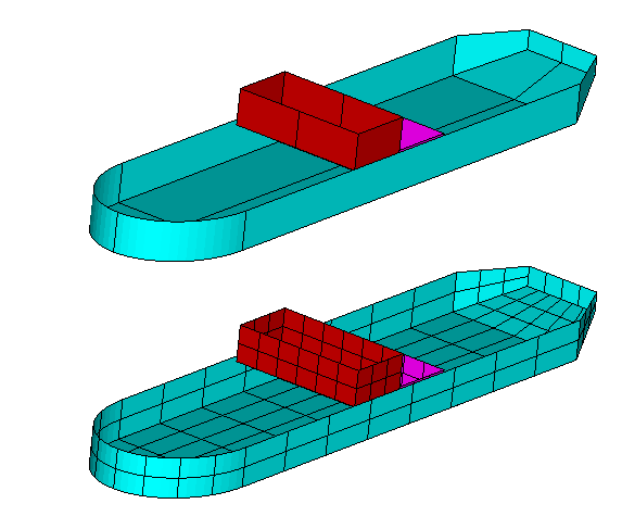
Input file: test22.cfg
! TEST22.CFG fpso with 2 interior tanks
ipltdat=4
ILOWHI=1
ILOG=1
ISOLVE=1
KSPLIN=3
IQUADO=3
IQUADI=4
MONITR=0
NUMHDR=1
NOOUT= 1 1 1 1 0 1 1 1 1
NPTANK=(8-11) (12-15)
RHOTANK= 1.0 1.0 (relative densities of tank fluids)
ITANKFPT=1 (tank field points are in .frc file)
Input file: test22.pot
TEST22.POT fpso with 2 interior tanks
-1.0
1 1 IRAD, IDIFF
3
2.0 2.5 3.0
1 NBETA (array BETA follows)
90.
1 NBODY
test22.gdf
0. 0. 0. 0. XBODY
1 1 1 1 1 1 IMODE(1-6)
Input file: test22.gdf
TEST22.GDF -- fpso with 2 tanks, one raised, joined at x=0
1. 9.80665 ULEN GRAV
0 1 ISX ISY
15 -21 NPATCH IGDEF
36 NLINES 4+16*2
3. 15. 2. XBOW, XMID, XAFT
2.2 1.2 HBEAM, HTRANSOM
1.2 0.6 DRAFT, DTRANSOM
0 0.0 INONUMAP, XBODY(3)
2.000000 0.000000 1.000000
2.000000 2.100000 1.000000
2.000000 2.100000 -0.100000
2.000000 0.000000 -0.100000 patch8 tank1 fwd
2.000000 2.100000 1.000000
0.000000 2.100000 1.000000
0.000000 2.100000 -0.100000
2.000000 2.100000 -0.100000 patch9 tank1 side
0.000000 0.000000 -0.100000
2.000000 0.000000 -0.100000
2.000000 2.100000 -0.100000
-0.000000 2.100000 -0.100000 patch10 tank1 bot
-0.000000 0.000000 -0.100000
-0.000000 2.100000 -0.100000
-0.000000 2.100000 1.000000
-0.000000 0.000000 1.000000 patch11 tank1 aft
0.000000 0.000000 0.000000
0.000000 2.100000 0.000000
0.000000 2.100000 -1.100000
0.000000 0.000000 -1.100000 patch12 tank2 fwd
0.000000 2.100000 0.000000
-2.000000 2.100000 0.000000
-2.000000 2.100000 -1.100000
0.000000 2.100000 -1.100000 patch13 tank2 side
-2.000000 0.000000 -1.100000
0.000000 0.000000 -1.100000
0.000000 2.100000 -1.100000
-2.000000 2.100000 -1.100000 patch14 tank2 bot
-2.000000 0.000000 -1.100000
-2.000000 2.100000 -1.100000
-2.000000 2.100000 0.000000
-2.000000 0.000000 0.000000 patch15 tank2 aft
Input file: test22.spl
TEST22.SPL FPSO with two tanks
4 3
4 2
8 3
8 2
2 1
3 3
3 2
3 2
3 2
3 3
3 2
3 2
3 2
3 3
3 2
Input file: test22.frc
TEST22.FRC fpso with 2 tanks, one field point on free surface in each tank
1 1 1 1 0 3 1 1 1
0.000000 VCG
1.000000 .0000000 .0000000
.0000000 1.000000 .0000000
.0000000 .0000000 1.000000 XPRDCT
0 NBETAH
2 NFIELD
1 1.0 1.0 1.0
2 -1.0 1.0 0.0
Input file: test22.csf
test22.csf FPSO, rectangular outer boundary
1 ILOWHICSF
0 1 ISX ISY
0 0 -2. NPATCH ICDEF PSZCSF (1st two indicate this is automatic)
0.0 2.0 RADIUS, DRAFT of outer box (0.0 signifies outer bdry defined below
1 NPART
4 nv0
12.0 0.0
12.0 3.0
-12.0 3.0
-12.0 0.0
THE FOLLOWING IS AN ALTERNATIVE CSF FILE WHICH IS NOT READ BY THE PROGRAM
UNLESS IT IS INTERCHANGED WITH THE FILE ABOVE.
test22.csf FPSO, circular outer boundary
1 ILOWHICSF
0 1 ISX ISY
0 0 2. NPATCH ICDEF PSZCSF (1st two indicate this is automatic)
12.0 2.0 RADIUS, DRAFT of outer box
0 NPART
In test22a the waterline is trimmed with a bow-up pitch angle of 6 degrees and a roll angle of 10 degrees, as shown in the figures. The draft is increased by 2m in the GDF file, and a vertical trim XTRIM(1)=2.0 is specified in the CFG file, giving a mean depth that is approximately the same as in test22. In this manner one ensures that the entire submerged portion of the hull surface is correctly defined. Since the draft is increased in the GDF file it is necessary to lower the tank bottoms by the same amount; thus the lower edges of the tank patches in test22a.gdf are 2m lower than in test22.gdf. With these inputs the waterline at the bow intersects both the vertical curved patch on the side of the bow and the flat bottom patch, with both end points on the curved side. The chine which connects these two patches in the untrimmed condition is submerged at the two ends, but above the free surface in the middle. For this reason it is necessary to assign the parameter ITRIMWL=2 in the cfg file. If ITRIMWL=1 is used the program will stop with an error message stating that part of patch 2 is above the free surface.
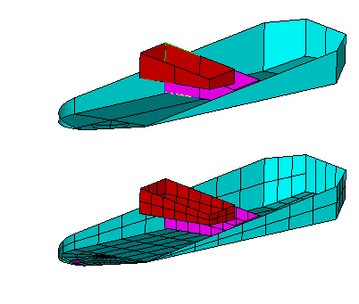
Input file: test22a.cfg
! TEST22a.CFG fpso with 2 interior tanks, trimmed waterline
ipltdat=4
ILOWHI=1
ILOG=1
ISOLVE=1
KSPLIN=3
IQUADO=3
IQUADI=4
MONITR=0
NUMHDR=1
NOOUT= 1 1 1 1 0 1 1 1 1
NPTANK=(8-11) (12-15)
RHOTANK= 1.0 1.0 (relative densities of tank fluids)
ITANKFPT=1 (tank field points are in .frc file)
ztankFS= 1.0 0.0
ITRIMWL=2
XTRIM=2.0 -6. 10.0
Input file: test22a.pot
TEST22a.POT fpso with 2 interior tanks, trimmed waterline
-1.0
1 1 IRAD, IDIFF
3
2.0 2.5 3.0
1 NBETA (array BETA follows)
90.
1 NBODY
test22a.gdf
0. 0. 0. 0. XBODY
1 1 1 1 1 1 IMODE(1-6)
Input file: test22a.gdf
TEST22.GDF -- fpso with 2 tanks, trimmed waterline
1. 9.80665 ULEN GRAV
0 1 ISX ISY
15 -21 NPATCH IGDEF
36 NLINES 4+16*2
3. 15. 2. XBOW, XMID, XAFT
2.2 1.2 HBEAM, HTRANSOM
3.2 2 .6 DRAFT, DTRANSOM
0 0.0 INONUMAP, XBODY(3)
2.000000 0.000000 1.000000
2.000000 2.100000 1.000000
2.000000 2.100000 -2.100000
2.000000 0.000000 -2.100000 patch8 tank1 fwd
2.000000 2.100000 1.000000
0.000000 2.100000 1.000000
0.000000 2.100000 -2.100000
2.000000 2.100000 -2.100000 patch9 tank1 side
0.000000 0.000000 -2.100000
2.000000 0.000000 -2.100000
2.000000 2.100000 -2.100000
-0.000000 2.100000 -2.100000 patch10 tank1 bot
-0.000000 0.000000 -2.100000
-0.000000 2.100000 -2.100000
-0.000000 2.100000 1.000000
-0.000000 0.000000 1.000000 patch11 tank1 aft
0.000000 0.000000 0.000000
0.000000 2.100000 0.000000
0.000000 2.100000 -3.10000
0.000000 0.000000 -3.10000 patch12 tank2 fwd
0.000000 2.100000 0.000000
-2.000000 2.100000 0.000000
-2.000000 2.100000 -3.10000
0.000000 2.100000 -3.10000 patch13 tank2 side
-2.000000 0.000000 -3.10000
0.000000 0.000000 -3.10000
0.000000 2.100000 -3.10000
-2.000000 2.100000 -3.10000 patch14 tank2 bot
-2.000000 0.000000 -3.10000
-2.000000 2.100000 -3.10000
-2.000000 2.100000 0.000000
-2.000000 0.000000 0.000000 patch15 tank2 aft
Input file: test22a.spl
TEST22a.SPL FPSO with two tanks, trimmed waterline
4 3
4 2
8 3
8 2
2 1
3 3
3 2
3 2
3 2
3 3
3 2
3 2
3 2
3 3
3 2
Input file: test22a.frc
TEST22A.FRC fpso with 2 tanks, one field point on free surface in each tank
1 1 1 1 0 3 0 1 1
0.000000 VCG
1.000000 .0000000 .0000000
.0000000 1.000000 .0000000
.0000000 .0000000 1.000000 XPRDCT
0 NBETAH
2 NFIELD
1 1.0 1.0 1.0
2 -1.0 1.0 0.0
In test22b the origin of the coordinate system is shifted to the bottom of the keel, with XBODY(3)=-1.2 assigned in the POT file and also in the GDF file. The geometry is unchanged from TEST22, except that the tops of the tanks are defined by two extra patches and the free surface elevations in the tanks are defined by the parameters ZTANKFS(1)=0.99 and ZTANKFS(2)=-0.01 in the CFG file. Thus the height filling ratios of the tanks are about 99%. Except for the roll and pitch moments and corresponding cross-coupling coefficients, which are affected by the coordinate shift, the hydrostatic and hydrodynamic outputs are close to the corresponding values in test22. Since XBODY(3) is nonzero the values of ZTANKFS in body coordinates, shown in the header of the output file test22b.out, differ from the inputs in global coordinates in the CFG file.
If the assignments of ZTANKFS and/or ITRIMWL are removed from the CFG file the tanks will be full, including the rigid tops, and there will be no free surface effects in the tanks. In that case the exciting forces and damping coefficients are unchanged, but the added-mass coefficients are different.
Input file: test22b.cfg
! TEST22b.CFG fpso with 2 interior tanks, trimmed to 99%
ipltdat=4
ILOWHI=1
ILOG=1
ISOLVE=1
KSPLIN=3
IQUADO=3
IQUADI=4
MONITR=0
NUMHDR=1
NOOUT= 1 1 1 1 0 1 1 1 1
NPTANK=(8-12) (13-17)
RHOTANK= 1.0 1.0 (relative densities of tank fluids)
ztankFS= 0.99 -0.01
ITRIMWL=1
Input file: test22b.pot
test22b.pot fpso with 2 interior tanks, rigid tops, xbody(3)=-1.2
-1.0
1 1 IRAD, IDIFF
3
2.0 2.5 3.0
1 NBETA (array BETA follows)
90.
1 NBODY
test22b.gdf
0. 0.0 -1.2 0. XBODY
1 1 1 1 1 1 IMODE(1-6)
Input file: test22b.gdf
test22b.GDF -- fpso with 2 tanks, with rigid tops, xbody(3)=-1.2
1. 9.80665 ULEN GRAV
0 1 ISX ISY
17 -21 NPATCH IGDEF npatch=7+2*5
44 NLINES 4+5*4*2
3. 15. 2. XBOW, XMID, XAFT
2.2 1.2 HBEAM, HTRANSOM
1.2 0.6 DRAFT, DTRANSOM
0 -1.2 INONUMAP, xbody(3)
2.000000 0.000000 1.000000
2.000000 2.100000 1.000000
2.000000 2.100000 -0.100000
2.000000 0.000000 -0.100000 patch8 tank1 fwd
2.000000 2.100000 1.000000
0.000000 2.100000 1.000000
0.000000 2.100000 -0.100000
2.000000 2.100000 -0.100000 patch9 tank1 side
0.000000 0.000000 -0.100000
2.000000 0.000000 -0.100000
2.000000 2.100000 -0.100000
-0.000000 2.100000 -0.100000 patch10 tank1 bot
-0.000000 0.000000 -0.100000
-0.000000 2.100000 -0.100000
-0.000000 2.100000 1.000000
-0.000000 0.000000 1.000000 patch11 tank1 aft
-0.000000 2.100000 1.000000
2.000000 2.100000 1.000000
2.000000 0.000000 1.000000
0.000000 0.000000 1.000000 patch12 tank1 top
0.000000 0.000000 0.000000
0.000000 2.100000 0.000000
0.000000 2.100000 -1.100000
0.000000 0.000000 -1.100000 patch13 tank2 fwd
0.000000 2.100000 0.000000
-2.000000 2.100000 0.000000
-2.000000 2.100000 -1.100000
0.000000 2.100000 -1.100000 patch14 tank2 side
-2.000000 0.000000 -1.100000
0.000000 0.000000 -1.100000
0.000000 2.100000 -1.100000
-2.000000 2.100000 -1.100000 patch15 tank2 bot
-2.000000 0.000000 -1.100000
-2.000000 2.100000 -1.100000
-2.000000 2.100000 0.000000
-2.000000 0.000000 0.000000 patch16 tank2 aft
-2.000000 2.100000 0.000000
0.000000 2.100000 0.000000
0.000000 0.000000 0.000000
-2.000000 0.000000 0.000000 patch17 tank2 top
Input file: test22b.spl
TEST22b.SPL FPSO with two tanks, rigid tops
4 3
4 2
8 3
8 2
2 1
3 3
3 2
3 2
3 2
3 3
3 2
3 3
3 2
3 2
3 3
3 2
3 3
Input file: test22b.frc
test22b.frc fpso with 2 tanks, xbody3=-1.2
1 1 1 1 0 0 1 1 1
0.000000 VCG
1.000000 .0000000 .0000000
.0000000 1.000000 .0000000
.0000000 .0000000 1.000000 XPRDCT
0 NBETAH
0 NFIELD
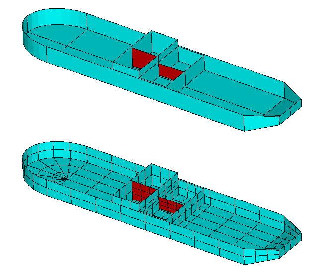
In Tests 22c and 22d dipole dampers are used in the tanks, in the same manner as in test07a, with the same full-scale dimensions and tank depths as in test07. The dipole dampers are shown in red in the figure above. In Test 22c IDAMPER=-1 is used, with the damping motion of the dipole surfaces represented by generalized modes as described in Section 12.8. The NEWMODES subroutine FLC_2D is used (IGENMDS=28) to define the generalized modes, using Legendre polynomials of order 8 in the vertical direction and order zero (constant) in the longitudinal direction. These parameters are specified in the file test22c_modes.dat. Since the principal motions in beam seas are heave, roll and sway the significant tank motions are transverse. At other angles of wave incidence where pitch and surge are significant it would be appropriate to use generalized modes for the dampers which include longitudinal variation. In Test 22d IDAMPER=2 is used with fixed dampers. Since the other inputs are the same, test22c.gdf is specified in the pot file. The results for the roll RAO and free-surface amplitude in the tanks are shown in Figure A.6, and can be compared with the low-order results in Figure A.3.
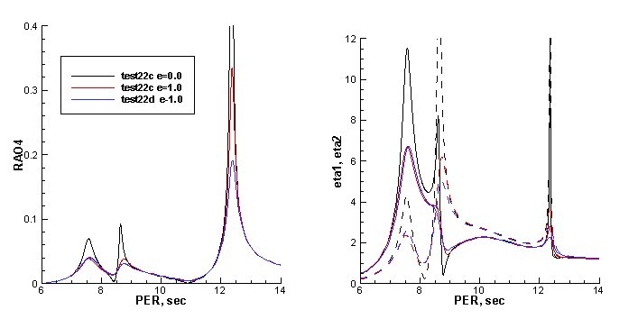
Input file: test22c.cfg
! TEST22c.CFG fpso with 2 tanks + dipole dampers
ipltdat=2
ILOWHI=1
ILOG=1
ISOLVE=1
KSPLIN=3
IQUADO=3
IQUADI=4
MONITR=0
NUMHDR=1
NOOUT= 1 1 1 1 0 1 1 1 1
NPTANK=(8-12) (13-17)
NPDIPOLE= 12 17 (dipole patches)
RHOTANK= 1.0 1.0 (relative densities of tank fluids)
idamper=-1 (use generalized modes for dampers)
ZTANKFS= 5. 0. (free-surface elevations in tanks)
ITRIMWL=1
ITANKFPT=1 (tank field points are in .frc file)
IGENMDS=28 (use newmodes subroutine FLC_2D)
NEWMDS = 16
Input file: test22c.pot
test22c.pot fpso with 2 tanks + dipole dampers, full scale
-1.0
1 1 IRAD, IDIFF
npergroup=5
-13
6.0 0.1
-173
7.25 .01
-31
9.0 0.1
-43
12.05 .01
-16
12.5 0.1
1 NBETA (array BETA follows)
90.
1 NBODY
test22c.gdf
0.0 0.0 0.0 0.0 XBODY
1 1 1 1 1 1 IMODE(1-6)
Input file: test22c.gdf
TEST22c.GDF -- fpso with 2 tanks + dipole dampers
1. 9.80665 ULEN GRAV
0 1 ISX ISY
17 -21 NPATCH IGDEF
44 NLINES 4+8*4
30. 150. 20. XBOW, XMID, XAFT
22. 12. HBEAM, HTRANSOM
12. 6.0 DRAFT, DTRANSOM
0 0.0 INONUMAP, XBODY(3)
20.0 0.0 6.0
20.0 21.0 6.0
20.0 21.0 -11.0
20.0 0.0 -11.0 patch8 tank1 fwd
20.0 21.0 6.0
0.0 21.0 6.0
0.0 21.0 -11.0
20.0 21.0 -11.0 patch9 tank1 side
0.0 0.0 -11.0
20.0 0.0 -11.0
20.0 21.0 -11.0
-0.0 21.0 -11.0 patch10 tank1 bot
-0.0 0.0 -11.0
-0.0 21.0 -11.0
-0.0 21.0 6.0
-0.0 0.0 6.0 patch11 tank1 aft
20.0 0.0 4.0
0.0 0.0 4.0
0.0 0.0 -10.0
20.0 0.0 -10.0 patch12 tank1 damper
0.0 0.0 6.0
0.0 21.0 6.0
0.0 21.0 -11.0
0.0 0.0 -11.0 patch13 tank2 fwd
0.0 21.0 6.0
-20.0 21.0 6.0
-20.0 21.0 -11.0
0.0 21.0 -11.0 patch14 tank2 side
-20.0 0.0 -11.0
0.0 0.0 -11.0
0.0 21.0 -11.0
-20.0 21.0 -11.0 patch15 tank2 bot
-20.0 0.0 -11.0
-20.0 21.0 -11.0
-20.0 21.0 6.0
-20.0 0.0 6.0 patch16 tank2 aft
0.0 0.0 -1.0
-20.0 0.0 -1.0
-20.0 0.0 -10.0
0.0 0.0 -10.0 patch17 tank2 damper
Input file: test22c.spl
TEST22c.SPL FPSO with 2 tanks + dipole dampers
4 3
4 2
8 3
8 2
2 1
3 3
3 2
3 2
3 2
3 3
3 2
3 3
3 2
3 2
3 3
3 2
3 3
Input file: test22c_modes.dat
test22c_modes.dat for 2 tank lids
1 2 Ibody Ndampers
12 12 IP1,IP2 for first tank
3 21 8 -10.0 4.0 z-direction Legendre order 8
1 21 1 0.0 20.0 x-direction Legendre order 1
2 2 odd in y -- all modes like sway
2 2
17 17 IP1,IP2 for 2nd tank
3 21 8 -10.0 -1.0 z-direction Legendre order 8
1 21 1 -20.0 0.0 x-direction Legendre order 1
2 2 odd in y -- all modes like sway
2 2
Input file: test22c.dmp
test22c.dmp file, edamper=1.0
2 ndampers
12 12 npdamper
1.0 edamper
17 17 npdamper
1.0 edamper
Input file: test22c.frc
test22c.frc fpso with 2 tanks + dipole dampers
1 1 1 1 0 1 0 0 0
0.000000 VCG
10.000000 .0000000 .0000000
.0000000 10.000000 .0000000
.0000000 .0000000 10.000000 XPRDCT
0 NBETAH
2 NFIELD
1 10.0 20.0 5.0
2 -10.0 20.0 0.0
Input file: test22d.cfg
! TEST22d.CFG fpso with 2 tanks + fixed dipole dampers
ipltdat=2
ILOWHI=1
ILOG=1
ISOLVE=1
KSPLIN=3
IQUADO=3
IQUADI=4
MONITR=0
NUMHDR=1
NOOUT= 1 1 1 1 0 1 1 1 1
NPTANK=(8-12) (13-17)
NPDIPOLE= 12 17 (dipole patches)
RHOTANK= 1.0 1.0 (relative densities of tank fluids)
idamper=2 (use fixed dampers)
ZTANKFS= 5. 0. (free-surface elevations in tanks)
ITRIMWL=1
ITANKFPT=1 (tank field points are in .frc file)
Input file: test22d.pot
test22d.pot fpso with 2 tanks + fixed dipole dampers
-1.0
1 1 IRAD, IDIFF
npergroup=5
-13
6.0 0.1
-173
7.25 .01
-31
9.0 0.1
-43
12.05 .01
-16
12.5 0.1
1 NBETA (array BETA follows)
90.
1 NBODY
test22c.gdf
0.0 0.0 0.0 0.0 XBODY
1 1 1 1 1 1 IMODE(1-6)
Input file: test22d.frc
test22d.frc fpso with 2 tanks + fixed dipole dampers
1 1 1 1 0 1 0 0 0
0.000000 VCG
10.000000 .0000000 .0000000
.0000000 10.000000 .0000000
.0000000 .0000000 10.000000 XPRDCT
0 NBETAH
2 NFIELD
1 10.0 20.0 5.0
2 -10.0 20.0 0.0
A.23 RADIATED WAVE FIELD FROM A BANK OF WAVEMAKERS – TEST23
Several variants are considered to illustrate the analysis of wavemakers in a wave tank.
In TEST23, following the procedure in Section 12.3, the option ISOLVE=-1 is used to compute the radiated waves from a bank of ‘paddle’ wavemakers. The wavemakers are in the plane x = 0 of a rectangular tank, as shown below. The tank has a reflecting wall at y = 0. The tank depth is 4m. Each wavemaker is represented by one rectangular patch, using IGDEF=0, with the vertices listed in TEST23.GDF. The motion of each wavemaker is rotational about its lower edge, at the same depth below the free surface, represented by a generalized mode with the same distribution of normal velocity and with symmetry prescribed about the walls x = 0 and y = 0. These generalized modes are defined in the subroutine WAVEMAKER, in the DLL file NEWMODES.F, designated by the parameter IGENMDS=21 in TEST23.CFG. This subroutine reads the depth of the lower edge of the wavemaker, ZHINGE=-2m, from the file WAVEMAKER_DEPTH.DAT. Wave elevations are evaluated at a square array of 64 field points defined in TEST23.FRC, using the uniform field point array option in Section 3.10.
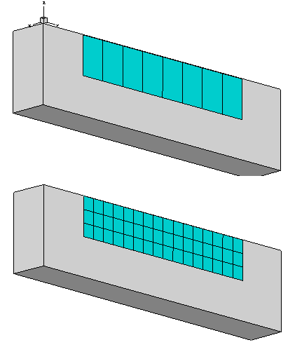
Input file: test23.cfg
! TEST23.CFG -- 8 wavemaker segments in wall x=0
ILOWHI=1
IALTFRC=2
ISOLVE=-1 (skip POTEN solutions for wavemakers in walls)
MONITR=0
NUMHDR=1
IGENMDS=21 (use NEWMODES subroutine WAVEMAKER)
PANEL_SIZE=1. (use default .spl parameters)
INUMOPT6=1 (output separate radiation modes in .6 file)
IFIELD_ARRAYS=1 (field points input in array format in .frc file)
ipltdat=4
NEWMDS = 8
Input file: test23.pot
TEST23.POT -- 8 wavemaker segments in wall x=0
4. fluid depth
0 -1 IRAD, IDIFF
2 NPER (array PER follows)
2. 4.
1 NBETA (array BETA follows)
0.0
1 NBODY
test23.gdf
0. 0. 0. 0. XBODY
0 0 0 0 0 0 IMODE(1-6)
First 10 lines of input file: test23.gdf
TEST23.GDF wavemaker, 8 segments in wall x=0 2<y<10m, ISY=1
1. 9.80665 ULEN GRAV
1 1 ISX ISY
8 0 NPATCH IGDEF
0.0000 2.000000 -2.00000
0.0000 3.00000 -2.00000
0.0000 3.00000 0.000000
0.0000 2.000000 0.000000 (end of Patch 1)
0.0000 3.000000 -2.00000
0.0000 4.00000 -2.00000
Input file: test23.frc
TEST23.FRC (field point wave elevations, IALTFRC=2, no external forces)
0 0 0 0 0 1 0 0 0 (IOPTN(1-9)
1. (RHO -- fluid density)
0. 0. 0. (XCG)
0 (IMASS)
0 (IDAMP)
0 (ISTIF)
0 (NBETAH)
0 (NFIELD -- no individual field points)
1 (NFIELD_ARRAYS -- number of arrays)
0 (Array is in exterior fluid domain)
8 2.5 1.0 (NFX, X1, DELX)
8 2.5 1.0 (NFY, Y1, DELY)
1 0.0 0.0 (NFZ, Z1, DELZ)
A.24 MOTIONS OF A HINGED VESSEL – TEST24
The subroutine CCYLHSP (IGDEF=-32) is used to generate a horizontal circular cylinder, with spheroidal ends, as shown below. The dimensions are specified in TEST24.GDF. Two planes of symmetry are specified. The cylinder is subdivided into five segments, to permit the analysis of a vessel with transverse hinges between the segments. Half of the middle segment and two others are in the domain x > 0. Four patches are required for these three elements plus the spheroidal end. The total number of segments, specified in TEST24.GDF, is used to read the x-coordinates of the boundaries between adjacent segments and also the end of the vessel. The total number of segments is equal to seven, including five cylinders plus two spheroids. Only the boundaries with coordinates x>0 are included in the last line of the GDF file, since ISX=1.
The generalized modes which represent the deflection of the hinges are defined in the subroutine HINGE_MODES in the DLL file NEWMODES.F, designated by the parameter IGENMDS=22 in TEST24.CFG. This subroutine reads the appropriate input data from the file test24_xhinge.dat, as described in Section 9.3. This input file specifies the symmetry index ISX=1, number of segments, and the x-coordinates of the hinges. The last cylinder and the spheroidal end are considered to be rigidly joined. Thus there are five ‘active’ segments corresponding to the parameter NSEG in the file, and NEWMDS=4 is assigned in the TEST24.POT file.
In the TEST24.FRC file, the 10×10 matrix of inertia coefficients is specified. No external damping or stiffness matrices are input, corresponding to the situation where the hinges are ideal without friction or other mechanical constraints.
Further information can be found in the headers and comments of the subroutines which are used to generate the geometry and to represent the hinge modes.
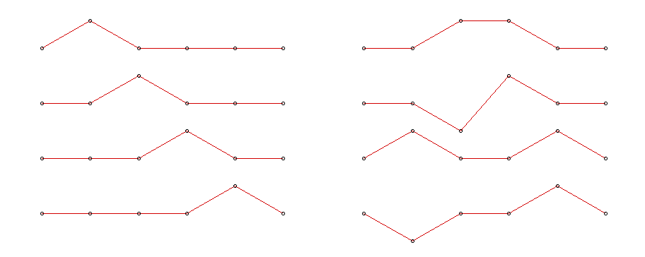
??
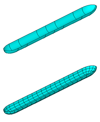
Input file: test24.cfg
! TEST24.CFG -- segmented vessel with 7 segments and 4 hinge modes
ipltdat=5
ILOWHI=1
IALTFRC=2
ISOLVE=1
IQUADI=4
IQUADO=3
KSPLIN=3
MONITR=0
NUMHDR=1
IGENMDS=22
NEWMDS = 4
Input file: test24.pot
TEST24 segmented vessel with 7 segments and 4 hinge modes
-1.
0 0 IRAD, IDIFF
2 NPER (array PER follows)
3. 5.
1 NBETA (array BETA follows)
180.
1 NBODY
test24.gdf
0. 0. 0. 0. XBODY
1 0 1 0 1 0 IMODE(1-6)
Input file: test24.gdf
TEST24 segmented vessel with 7 segments
1. 9.80665 ULEN GRAV
1 1 ISX ISY
4 -32 NPATCH IGDEF
3 NLINES
7 Nsegments
1. Radius
2. 6. 8. 10. xseg
Input file: test24.spl
TEST24 segmented vessel with 7 segments
4 2 NU NV mid cylinder
4 4 next cylinder
4 2 outer cylinder
4 4 spheroidal end
Input file: test24.frc
TEST24 segmented vessel with 7 segments and 4 hinge modes
1 1 1 1 0 0 0 0 0
1000.
0. 0. 0.
1
29321.5 0. 0. 0. 0. 0. 0. 0. 0. 0.
0. 29321.5 0. 0. 0. 0. 0. 0. 0. 0.
0. 0. 29321.5 0. 0. 0. 12000. 0. 12000. 0.
0. 0. 0. 1.5E4 0. 0. 0. 0. 0. 0.
0. 0. 0. 0. 7.33E5 0. 0. -24000. 0. -72000.
0. 0. 0. 0. 0. 7.33E5 0. 0. 0. 0.
0. 0. 12000. 0. 0. 0. 10000. 0. 2000. 0.
0. 0. 0. 0. -24000. 0. 0. 6000. 0. 2000.
0. 0. 12000. 0. 0. 0. 2000. 0. 8000. 0.
0. 0. 0. 0. -72000. 0. 0. 2000. 0. 8000.
0
0
0
0
A.25 AIR-CUSHION VESSEL WITH PRESSURE CHAMBERS – TEST25
The vessel consists of two air chambers surrounded by rectangular skirts. The length is 20m, beam 10m and draft 2m. The width of the skirts is 1m. The free surface in the chambers, shown by red shading in the figures below, is 1m below the exterior free surface. One quadrant of these surfaces is represented by flat quadrilateral patches in the GDF file, with two planes of symmetry. Two pressure modes are used to represent anti-symmetric and symmetric pressure distributions with constant pressure in each chamber, denoted by Modes 7 and 8 respectively. These pressure modes are defined by the NEWMODES subroutine PRESSURE_FS. The configuration parameter ICCFSP=1 is used to include the external restoring coefficients due to the pressure acting on the upper surface of the air chambers (see Section 12.5).
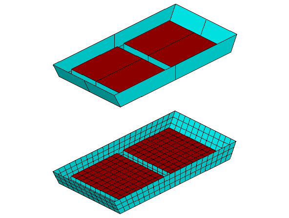
Input file: test25.cfg
! TEST25.CFG -- ACV (air-cushion vehicle) with 2 air chambers
ipltdat=1
ILOWHI=1
IALTFRC=1
ISOLVE=1
PANEL_SIZE = 1.0 (use default .spl parameters)
NUMHDR=1
IMODESFSP=1 (use NEWMODES subroutine PRESSURE_FS)
NMODESFSP=2 (2 pressure modes, sym & antisym about x=0)
NPFSP=(9 9) (free surface pressure on patch 9)
ICCFSP=1 (include external restoring coefficients)
Input file: test25.pot
TEST25 ACV (air-cushion vehicle) with 2 air chambers
-1.
0 1 IRAD, IDIFF
6 NPER (array PER follows)
5.0 6.0 7.0 8.0 9.0 10.0
1 NBETA (array BETA follows)
180.
1 NBODY
test25.gdf
0. 0. 0. 0. XBODY
1 0 1 0 1 0 IMODE(1-6)
First 10 lines of input file: test25.gdf
TEST25 ACV (air-cushion vehicle) with 2 air chambers - igdef=0
1.00 9.80665
1 1
9 0 NPATCH, IGDEF
9.00 0.00 -2.00
9.00 5.00 -2.00
10.00 5.00 0.00
10.00 0.00 0.00 (end)
9.00 5.00 -2.00
0.00 5.00 -2.00
Input file: test25.frc
TEST25.FRC ACV (air-cushion vehicle) with 2 air chambers
1 1 1 1 0 0 0 0 0 IOPTN(1-9)
0.000000 VCG
2.500000 .0000000 .0000000
.0000000 5.000000 .0000000
.0000000 .0000000 5.000000 XPRDCT
0 NBETAH
0 NFIELD