1.1 WAMIT Version 7
1.2 Changes Introduced in Version 7.0
1.3 Changes Introduced in Version 7.1
1.4 Changes Introduced in Version 7.2
1.5 Changes Introduced in Version 7.3
1.6 Changes Introduced in Version 7.4
2 Getting Started
2.1 Installation and Setup
2.2 WAMIT DEMO Program
2.3 Standard Test Runs
2.4 Running TEST01
2.5 Running TEST11
2.6 Other Test Runs
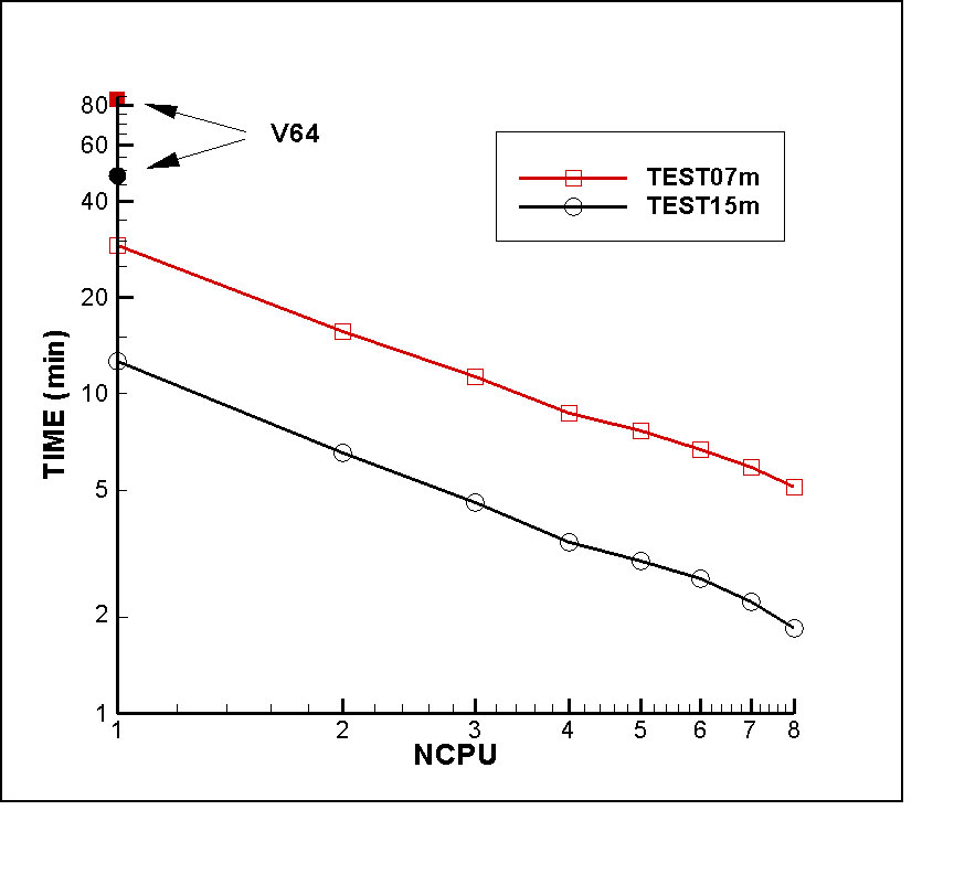
2.7 Using Multiple Processors
2.8 Memory and Storage Restrictions
2.9 Modifying Input Files
3 Definition of WAMIT Quantities
3.1 Hydrostatic Data
3.2 Added-Mass and Damping Coeff
3.3 Exciting Forces
3.4 Body Motions in Waves
3.5 Hydrodynamic Pressure
3.6 Free-Surface Elevation
3.7 Body & Fluid Domain Velocity Vector
3.8 Mean Drift Force and Moment
3.9 Zero and Infinite Wave Periods
4 Input Files
4.1 Summary of Changes in Input Files
4.2 The Potential Control File (.POT)
4.3 The Force Control File (.FRC, Alt. 1)
4.4 The Force Control File (.FRC, Alt. 2)
4.5 Definition of Fixed or Free Modes
4.6 Body Pressure and Fluid Velocity at Specified Points
4.7 Configuration Files
4.8 Filenames List FNAMES.WAM
4.9 File Name Rules
4.10 File Format
4.11 Uniform Arrays of Field Points
4.12 BREAK.WAM File
4.13 Assigning RAO’s
4.14 Evaluating Outputs in POTEN (IFORCE=2)
5 Output Files
5.1 The Formatted Output File (OUT)
5.2 Numeric Output Files
5.3 Froude-Krylov & Scattering Forces
5.4 Body Pressure for the Higher-Order Method
5.5 Body Pressure & Velocity at Specified Points
5.6 Auxilary Hydrostatic (HST) and External Force (MMX) Files
5.7 Auxiliary Output Files for the Geometry
5.8 Error Messages
5.9 The Log File (wamitlog.txt)
5.10 The Intermediate Data Transfer File (P2F)
6 The Low-Order Method (ILOWHI=0)
6.1 The Geometric Data File
6.2 Use of the Source Formulation (ISOR=1)
6.3 Bodies with Thin Submerged Elements
7 The Higher-Order Method (ILOWHI=1)
7.1 Subdivision of the Body Surface in Patches & Panels
7.2 B-Spline Representation of the Solution
7.3 Order of Gauss Quadratures
7.4 The Geometric Data File
7.5 Low-Order Panel Geometry (IGDEF=0)
7.6 B-Spline Geometry Representation (IGDEF=1)
7.7 Multisurf Geomtry (IGDEF=2)
7.8 Analytic Geometry
7.9 Modifying GEOMXACT.DLL
7.10 Bodies with Thin Submerged Elements
7.11 The Optional Spline Control File
7.12 Using Default Values
7.13 Comments on the Higher-Order Method
8 Analysis of Multiple Bodies
8.1 Input to Force (IALTFRC=1)
8.2 Input to Force (IALTFRC=2)
8.3 Input to Force (IALTFRC=3)
8.4 Parameters in Configuration Files
8.5 Global Symmetry Indices
8.6 Output
9 Generalized Body Modes
9.1 Input Files
9.2 Using DEFMOD & Low-Order Method
9.3 Using NEWMODS.DLL
9.4 Hydrostatics
9.5 NBODY Analysis
10 Use of Irregular Frequency Option
10.1 Input Parameters
10.2 Automatic Free-Surface Discretization (IRR=2 & ILOWHI=0)
10.3 Automatic Free-Surface Discretization (IRR=3 & ILOWHI=0)
10.4 Automatic Free-Surface Discretization (IRR=3 & ILOWHI=1)
10.5 Assigning Different Values of IRR
11 Mean Drift Forces Using Control Surfaces
11.1 Control Surface File (CSF)
11.2 Low-Order CSF
11.3 High-Order CSF
11.4 Combining Two CSF
11.5 Automatic Control Surfaces
11.6 Output
12 Special Extensions
12.1 Internal Tanks
12.2 Trimmed Waterlines
12.3 Radiated Waves from Wavemakers in Tank Walls
12.4 Bodies and Wavemakers with Vertical Walls
12.5 Bodies with Pressure Surfaces
12.6 Integrating Pressure on Part of Bodies
12.7 Bodies in Channels of Finite Width
12.8 Fluid Damping Surfaces
13 The F2T Utility
13.1 Radiation and Diffraction Outputs
13.2 Input Data for F2T using WAMIT
13.3 How to use F2T
13.4 F2T Output Files
13.5 Options 5 & 6
13.6 Theory
13.7 Dimensional Input and Output Data
14 Computational Topics
14.1 NEQN & NLHS
14.2 Solution of the Linear Systems
14.3 Temporary Data Storage
14.4 Data Storage in RAM
14.5 Data Storage in Scratch Files
14.6 Multple Processors
14.7 Modifying DLL Files
14.8 Reserved File Names
14.9 Large arrays of field points
15 Theory
15.1 The Boundary-Value Problem
15.2 Integral Equations for the Velocity Potential
15.3 Discretization in the Low-Order Method
15.4 Integral Equations for the Source Formulation
15.5 Discretization in the Higher-Order Method
15.6 Removal of Irregular Frequencies
15.7 Integral Equations for Bodies with Thin Submerged Elements
15.8 Mean Drift Forces Based on Pressure Integration
15.9 Mean Drift Forces Using Control Surfaces
15.10 Internal Tank Effects
15.11 Bodies with Pressure Surfaces
15.12 Low-frequency limits in finite depth
15.13 Fluid Damping Surfaces
REFERENCES
A Test Run Descriptions
A.1 TRUNCATED VERTICAL CYLINDER – TEST01
A.2 CYLINDER & MOONPOOL – TEST02
A.3 TWO BARGES WITH A SMALL GAP – TEST03
A.4 BODY IN A CHANNEL OR NEAR A WALL – TEST04
A.5 MULTIPLE BODIES – TEST05
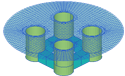
A.6 THE ISSC TENSION-LEG PLATFORM – TEST06
A.7 FPSO WITH TWO INTERNAL TANKS – TEST07
A.8 ELASTIC COLUMN WITH GENERALIZED MODES – TEST08
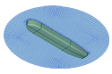
A.9 SPAR WITH THREE STRAKES – TEST09
A.11 CIRCULAR CYLINDER – TEST11
A.12 IRREGULAR-FREQUENCY REMOVAL – TEST12
A.13 MULTIPLE BODIES – TEST13
A.14 ISSC TLP – TEST14
A.15 SEMI-SUB – TEST15
A.16 BARGE WITH BENDING MODES – TEST16
A.17 CYLINDER WITH MOONPOOL – TEST17
A.18 ELASTIC COLUMN – TEST18
A.19 CATAMARAN BARGE – TEST19
A.20 MULTISURF BARGE – TEST20
A.21 SPAR WITH THREE STRAKES – TEST21
A.22 FPSO WITH TWO INTERNAL TANKS – TEST22
A.23 RADIATED WAVE FIELD FROM A BANK OF WAVEMAKERS – TEST23
A.24 MOTIONS OF A HINGED VESSEL – TEST24
A.25 AIR-CUSHION VESSEL WITH PRESSURE CHAMBERS – TEST25
B File Conversion using V6V7inp